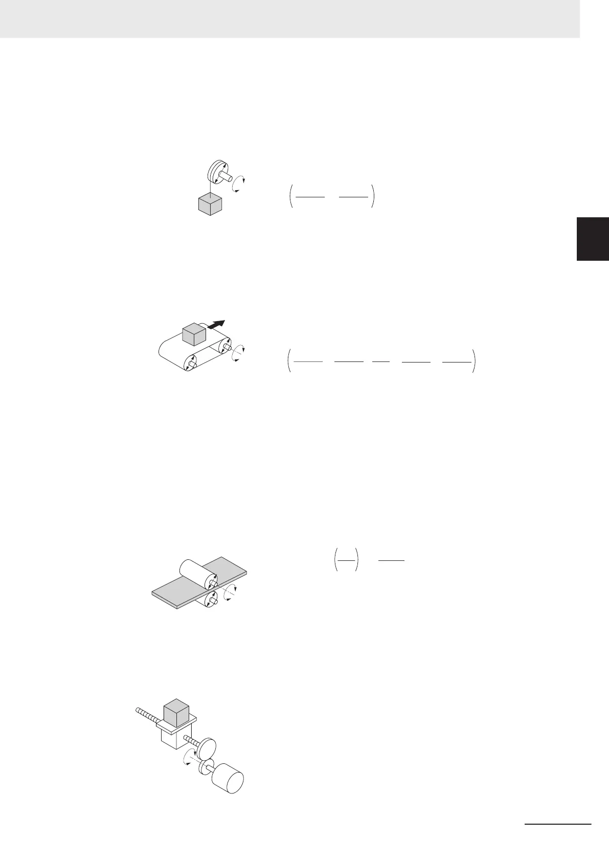
Calculation of load inertia and motor-shaft conversion inertia
Depending on the type of the motor transfer system, calculate the inertia for all parts and convert it
into the motor-shaft inertia.
• Example in hoist application
× 10
-6
4
M
· D
2
+
8
M! · D
2
=
= J! + J
J" [kg·m
2
]
J"
: Shaft conversion inertia [kg·m
2
]
J!
: Inertia of cylinder (Shaft conversion) [kg·m
2
]
J
: Inertia of workpiece (Shaft conversion) [kg·m
2
]
M!
: Mass of cylinder [kg]
M : Mass of workpiece [kg]
D : Diameter of cylinder [mm]
J"
M!
M
D
• Example in conveyor application
J
: Shaft conversion inertia (Cylinder-1-shaft conversion) [kg·m
2
]
J : Inertia of cylinder 1 (Cylinder-1-shaft conversion) [kg·m
2
]
J : Inertia of cylinder 2 (Cylinder-1-shaft conversion) [kg·m
2
]
J : Inertia of workpiece (Cylinder-1-shaft conversion) [kg·m
2
]
J : Inertia of belt (Cylinder-1-shaft conversion) [kg·m
2
]
M : Mass of cylinder 1 [kg]
M
: Mass of cylinder 2 [kg]
M : Mass of workpiece [kg]
M : Mass of belt [kg]
D : Diameter of cylinder 1 [mm]
D : Diameter of cylinder 2 [mm]
4
M · D
2
+
4
M · D
2
+
D
2
D
2
·
× 10
-6
8
M · D
2
+
8
M ·D
2
=
= J
+ J
+ J
+ J
J[kg·m
2
]
J
D
M
M
M
MD
• Example in roller application
J : Shaft conversion inertia (Roller-1-shaft convers
ion) [kg·m
2
]
J : Inertia of roller 1 (Roller-1-shaft conversion) [kg·m
2
]
J : Inertia of roller 2 (Roller-2-shaft conversion) [kg·m
2
]
M : Mass of workpiece [kg]
D : Diameter of roller 1 [mm]
D : Diameter of roller 2 [mm]
× 10
-6
4
M · D
2
J +
D
2
D
2
= J +
J [
kg·m
2
]
J
D
J
M
J
D
• Example of conversion into motor-shaft inertia
J
[kg·m
2
] = J
+ G
2
(J + J)
J
: Motor-shaft conversion inertia [kg·m
2
]
J
: Load inertia (Load-side gear-shaft conversion) [kg·m
2
]
J
: Inertia of motor-side gear [kg·m
2
]
J
: Inertia of load-side gear [kg·m
2
]
Z
: Number of motor-side gear teeth
Z
: Number of load-side gear teeth
G : Gear ratio (Speed reduction ratio) = Z / Z
Load-side gear J
Motor-side gear J
J
Load J
Motor
Appendix
A-11
M1 Series Standard Type User's Manual (I669)
A-4 Overview of Inverter Selection
A
A-4-1 Motor Capacity Selection

 Loading...