1-13
1 Introduction to NJ-series Controllers
NJ-series CPU Unit Software User’s Manual (W501)
1-3 Overall Operating Procedure
for the NJ-series Controller
1
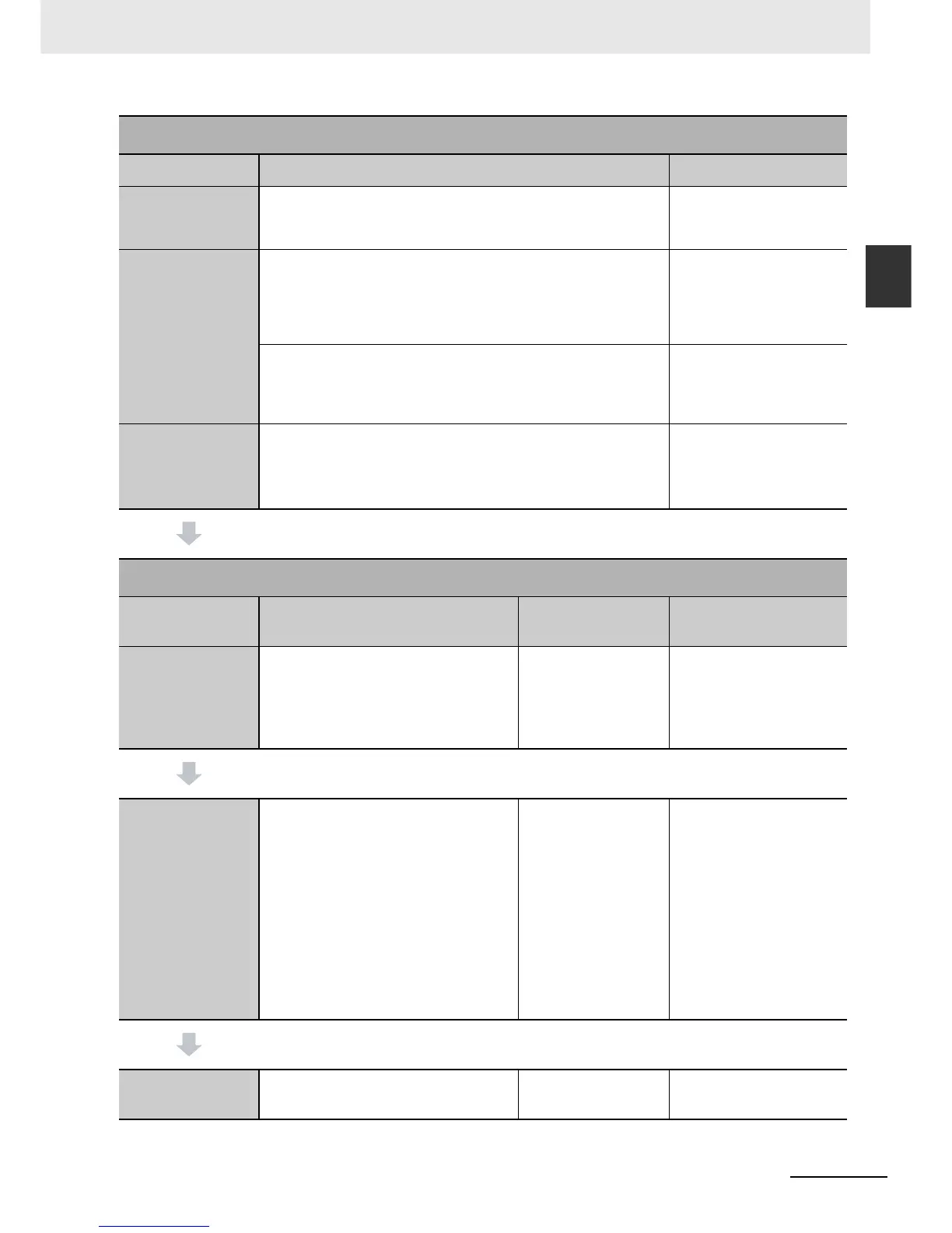
1-3-2 Procedure Details
* Use the Synchronize Menu of the Sysmac Studio to download the project.
Step 4. Wiring
Step Description Reference
1. Connecting
Ethernet Cable
• Connecting the built-in EtherCAT port
• Connecting the built-in EtherNet/IP port
4-4 Wiring in NJ-series CPU
Unit Hardware User’s Man-
ual (Cat. No. W500)
2. Wiring I/O
• Wiring I/O to EtherCAT slaves
• Wiring Basic I/O Units and Special Units
Operation manuals for the
EtherCAT slaves and 4-4
Wiring in NJ-series CPU
Unit Hardware User’s Man-
ual (Cat. No. W500)
• Checking wiring
6-4-2 Performing Online
Debugging in Sysmac Stu-
dio Version 1 Operation
Manual (Cat. No. W504)
3. Connecting the
Computer That
Runs the Sysmac
Studio
• Connecting USB Cable
• Connecting the built-in EtherNet/IP port
Sysmac Studio Version 1
Operation Manual (Cat. No.
W504)
Step 5. Checking Operation and Starting Operation on the Actual System
Step Description Sysmac Studio
Operations
Reference
1. Online Connec-
tion to Sysmac Stu-
dio and Project
Download
Turn ON the power supply to the Controller
and place the Sysmac Studio online.
Then, download the project.*
(Perform this step before you create the
slave configuration or Unit configuration
from the mounted Units in step 2-1.)
Controller
Commu-
nications Setup
Controller
Synchro-
nization
Section 7 Checking Opera-
tion and Actual Operation
2. Operation Check
on Controller
1. Check the wiring by using forced
refreshing of real I/O from the I/O Map
or Watch Tab Page.
2. For motion control, use the MC Test
Run operations in PROGRAM mode to
check the wiring. Then check the motor
rotation directions for jogging, travel
distances for relative positioning (e.g.,
for electronic gear settings), and hom-
ing operation.
3. Change the Controller to RUN mode
and check the operation of the user
program.
Section 7 Checking Opera-
tion and Actual Operation
3. Actual Controller
Operation
Start actual operation. Section 7 Checking Opera-
tion and Actual Operation

 Loading...


