90
Chapter4
OS32C
User’s Manual
Installation
Calculation Example of Safety Distance S
S = (K x T) + C + Z
= 1600 mm/s x (0.08 s+0.2 s) + (1200 mm - (0.4 x 300 mm)) + 100 mm
= 448 mm + 1080 mm +100 mm
= 1628 mm
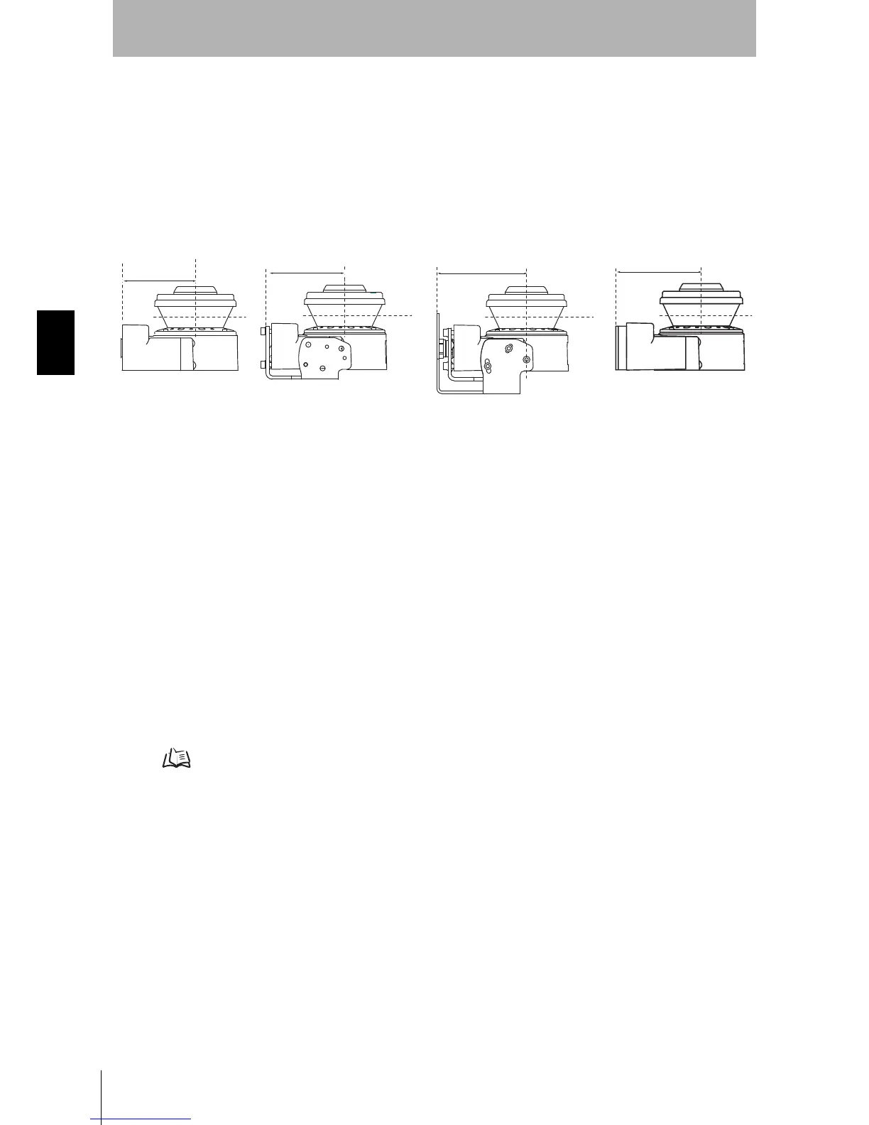
There are several different ways to install the OS32C as shown in Fig. 4-8. Each length of SFdistance
(the potential dead space indicated in Fig. 4-7 between the OS32C and the danger zone) is different.
Fig. 4-8 Dimensions of SFdistance
Take additional precautions to prevent intrusion to the dead zone after determining how to mount the
OS32C.
Additional Error Z2 due to Reflective Background
(1) High-reflective background material or object is present in the scanning plane and within 1.2m
beyond the safety zone.
(e.g. acrylic panel, stainless steel, reflective tape, mirror)
(2) Low-reflective background material or object is present in the scanning plane and within 1.2m
beyond the safety zone.
(e.g. paint-finished equipment)
If any of the conditions listed above apply to your application, an additional error factor Z
2 should be
added to the safety zone.
Additional Error due to Reflective Background p.131
111.4mm
97.7mm
90.4mm
OS32C only OS32C with OS32C-BKT1 OS32C with OS32C-BKT1 & OS32C-BKT2 OS32C with OS32C-BKT3
103.4mm
 Loading...