14
Chapter2
OS32C
User’s Manual
Operating States & Output Modes
Operating States
The following operating states exist for the OS32C system.
1. OSSD ON State
The two safety outputs are in the ON state, and the machine run (green) indicator is lit. The protected machine
is allowed to operate. The state/diagnostic display indicates a state of monitoring zone set selection and a
response time.
2. OSSD OFF State
An object exists in a safety zone and it is being detected. The two safety outputs are in the OFF state, and the
machine stop (red) indicator and the intrusion indicators in the affected region(s) are lit. The protected
machine is not allowed to operate. The status/diagnostic display shows "- -".
3. Interlock State
This state waits for a start input (See p.17 for details.). The two safety outputs are in the OFF state, the red
STOP indicator and yellow interlock indicator are lit. The protected machine is not allowed to operate. The
status/diagnostic display shows "01".
4. Lockout State
A failure is being detected and the guarded machine is being stopped. The two safety outputs are in the OFF
state, the machine stop (red) indicator is lit and yellow interlock indicator is flashing. The protected machine is
not allowed to operate. The status/diagnostic display shows the error code that caused the lockout. The
OS32C system will remain in the lockout state until the problem is corrected and a start input is applied or
power on the unit is cycled.
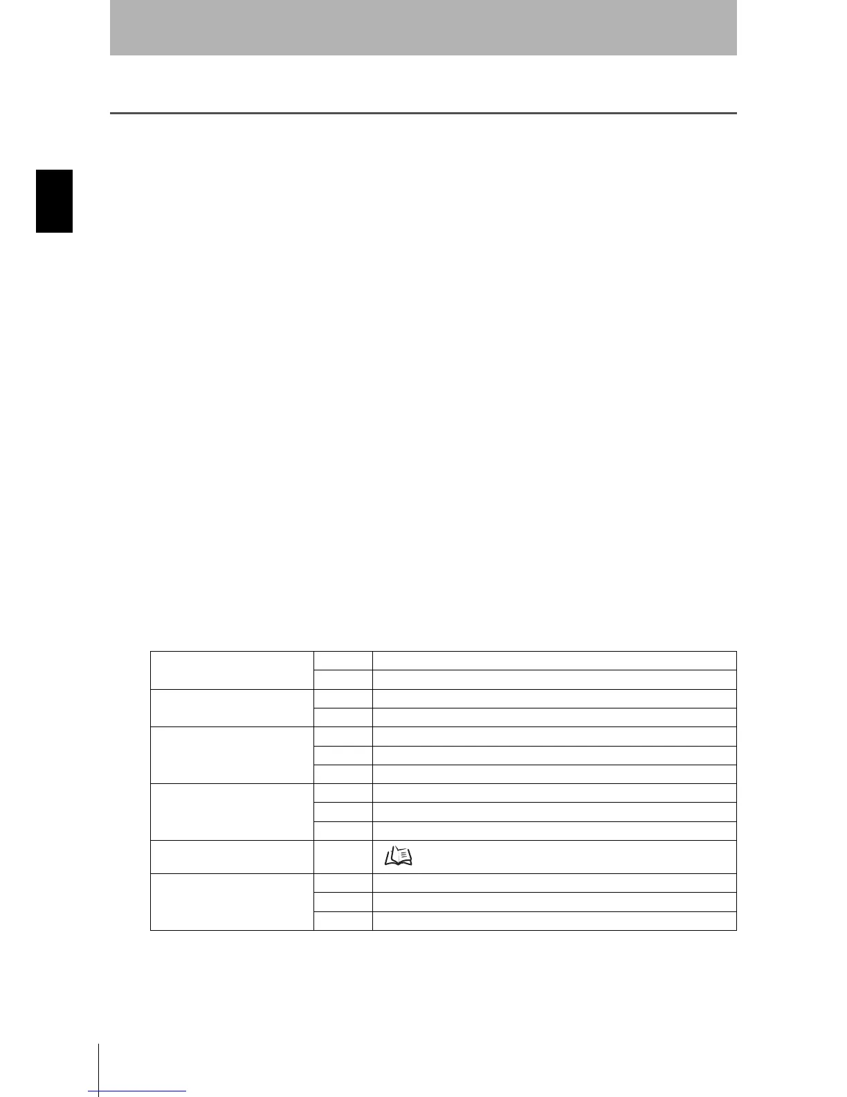
Indication Patterns
Table 2-1 Indication Patterns
RUN indicator
(Green LED)
On When OSSD is ON
Off When OSSD is OFF
STOP indicator
(Red LED)
On When OSSD is OFF
Off When OSSD is ON
Interlock Indicator
(Yellow LED)
On Interlock State
Flashing Lockout State (@ 1Hz), Configuration State (@ 4Hz)
Off Other than the above
Warning output indicator
(Orange LED)
On When any warning zone is intruded
Flashing When dust or contamination is detected on the scan window (@ 1 Hz)
Off Other than the above
Status/Diagnostic Display
See "OS32C Status Check" on page 129.
Individual Sector Indicators
(Red LED)
On When an object is in any safety or warning zone. *1, *2
Flashing When dust or contamination is detected on the scan window. *1
Off Zones are clear and window is clean.
*1 The functionality of the intrusion indicators is configurable via the configuration tool.
*2 The intrusion indicators in the affected region is lit or flashing.
 Loading...