114
Chapter5
OS32C
User’s Manual
Wiring
Input/Output Signal
The tables below reference the connections on the OS32C. They are identified by the pin number, input type,
and input name.
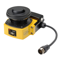
Fig. 5-1 Power Control 18-Pin Mini-Type Connector
The table below cross-references the Power/Control connector pin out and to the mating cable conductor
color and signal description.
Table5-1 Power and Input/Output Connections
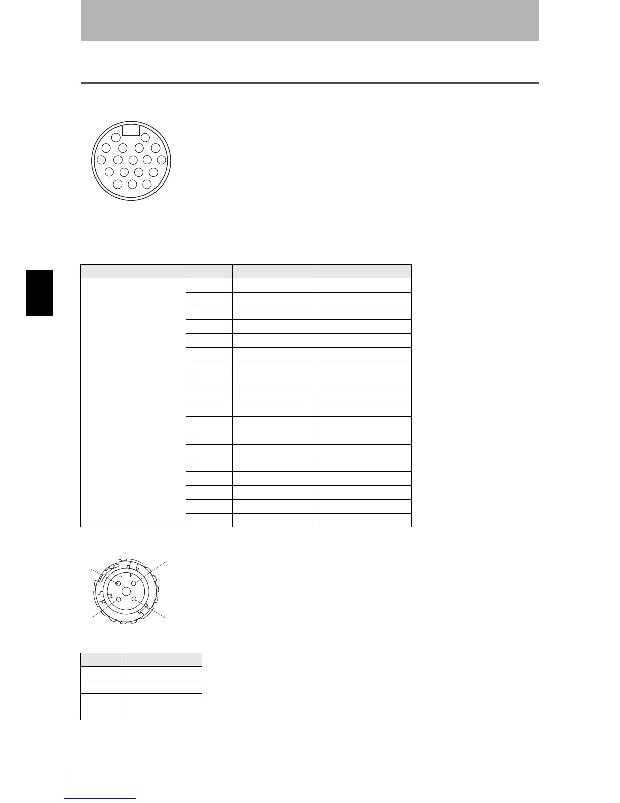
Fig. 5-2 Ethernet Port
Table5-2 PC Interface Connections M-12, 4-Pin, Female
Connector Pin Conductor Colors Signal Name
18 Pins Mini-Type Connector
1 Orange/White Zone Select 1
2 Orange/Black Zone Select 2
3 Gray Zone Select 3
4 Pink Zone Select 4
5BlackStart
6 Violet Standby input
7 Blue Auxiliary Output
8 Red/Black Warning Output
9 Red OSSD A
10 Yellow OSSD B
11 Blue/White Zone Select 8
12 White +24V
13 White/Black Zone Select 5
14 Brown 0V
15 Brown/White EDM
16 Tan Zone Select 6
17 Orange Zone Select 7
18 Green Functional earth
Pin Signal Name
1+TX
2+RX
3-TX
4-RX
 Loading...