ED1 ED2
S2
S3
S2
S1
M1
ED1
ED2
0V
E1
0VDC (Brown)
Standby input (Violet)
Zone Select 1 (Orange/White)
Zone Select 2 (Orange/Black)
Zone Select 3 (Gray)
Start (Black)
Auxiliary output(Blue)
Warning output (Red/Black)
EDM (Brown/White)
Safety output B (Yellow)
Safety output A
(Red)
* 3
*4
*4
* 1
* 1
* 2
+24V
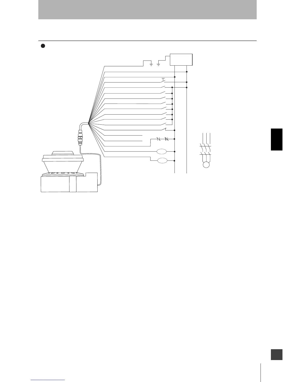
Basic connection (with single OS32C unit)
Category 3, Performance Level d (ISO13849-1)
S1 : Start Input
S2 : Zone Select Switch
S3 : Standby Switch
ED1, ED2: Forced guided relay
M1 : 3-Phase Motor
E1 : 24 VDC Power
Functional Earth (Green)
24VDC (White)
OS32C Configuration
- External Device Monitoring
Enabled
- Start/Restart Interlock
Zone Select 4 (Pink)
Zone Select 5 (White/Black)
S2
*4
S2
*4
S2
*4
*4
*4
*4
Zone Select 6 (Tan)
Zone Select 7 (Orange)
Zone Select 8 (Blue/White)
S2
S2
S2
*1. The External Devices ED1 and ED2 are force-guided relays. (e.g. G7Z, G7SA or G7S)
*2. If the External Device Monitoring is not used, connect brown/white wires to 0V,
The Start Input must be a Normally Closed switch.
*3.
and then turn OFF the External Device Monitoring with the configuration software.
*4.
ED1
ED2
PE
For zone select switch setting, see Zone Set Input Selection. When using only one zone, no connection
is needed for the zone select inputs.

 Loading...