4
Chapter1
OS32C
User’s Manual
Description of Use and Features
System Components
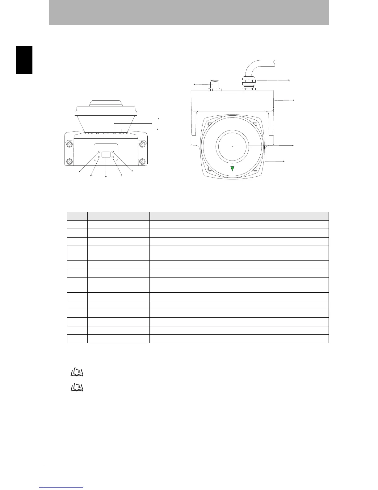
Fig. 1-1 System Components
*1: The communication and power connections can also be mounted on the left side of the I/O block.
Table 1-1 System Components and Indicators
For details on indicators, refer to "Indication Patterns" on page 14.
For details on Status/Diagnostic Display, refer to "OS32C Status Check" on page 129.
Number Component Function
(1) RUN indicator (green) Will turn ON when safety zone is clear and OSSDs are ON.
(2) Interlock Indicator (yellow) Will turn ON when in interlock state, blink under lockout, and blink in case of a failure.
(3) Status/Diagnostic Display The scanner's status ,configuration/operation, or failure is displayed
(4)
Warning Output Indicator
(orange)
Will turn ON when the warning output is ON.
(5) STOP indicator (red) Will turn ON when safety zone is blocked, OSSD are OFF or under interlock state.
(6) Dust Ring Dust detection cover with reflective surface, for dust accumulation detection
(7)
Individual Sector Indicators
Will turn ON when an intrusion is detected in the safety zone, 8 sectors total. Each sector =
33.75°.
(8) Scan Window The window where the laser light is emitted and received.
(9) Communication Connector Provides for Ethernet interface.*1
(10) Power Connector For power connections, 18-pin connector (pigtail).*1
(11) I/O Block Connector module
(12) Center of rotation Indicates the location of the axis around which the laser irradiates from.
(13) Sensor Sensor head; field replaceable.
 Loading...