EasyManua.ls Logo

Omron OS32C Series User Manual

Omron OS32C Series
167 pages
To Next Page IconTo Next Page
To Previous Page IconTo Previous Page
Page #46 background imageLoading...
Page #46 background image
26
Chapter2
OS32C
User’s Manual
Operating States & Output Modes
2) Zone Set Select Input Switch Timing - The worst case time it can take for switching zone set
select inputs. This time starts on the transition on the first input change and ends to the transition
on the last input change, this will be defined as T
switches.
3) Zone Set Select Input Switch Tolerance - It is required that the zone set select input switching
circuitry begin switching the zone set inputs at a precise time relative to when the zone set
transition is desired to occur. The tolerance of timing when input state is actually switched,
generated by input switching circuitry, will be defined using +/- T
tol.
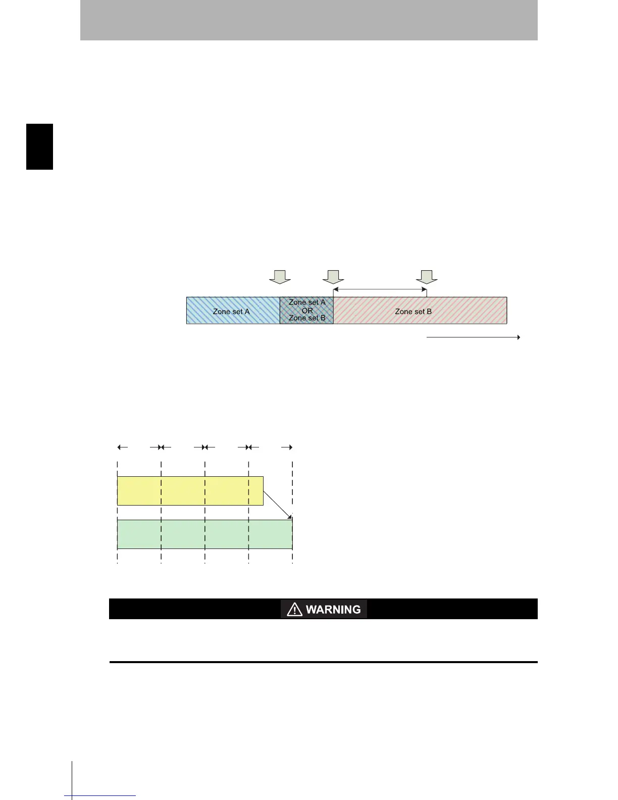
The simplest monitoring zone set switching timing in an installation is t
EndZoneA < tStartZoneB. In this case,
the interval between t
EndZoneA and tEndZoneA does not require any monitoring, thus switching from zone
set A to zone set B is straightforward. But when t
EndZoneA = tStartZoneB or tEndZoneA > tStartZoneB, both zone set
A and zone set B may need to be monitored simultaneously. In such case, refer to How to Guarantee
Protection of Original Zone Set.
Fig. 2-8 Switch from Zone set A to Zone set B.
The Zone Set Input Switch Timing must be configured to consider delay time of input switching circuitry
and ensure proper monitoring and safety. The configuration parameter Zone Set Switching Delay
(T
delay) needs a value larger than Tswitches in increments of 20 ms (Tsample). In the following example,
T
delay is configured to 80ms or more.
Fig. 2-9 Zone Delay configuration.
If an insufficient Zone Delay is used for the actual worst case zone set select input switching time of the
installation, an unintended zone set may be temporarily enabled, resulting in temporarily monitoring
the wrong zone.
Also, it must be ensured that after a zone switch there is a minimum "hold time" before the next zone
switch can take place. That time is 2 * T
sample.
Zone set B Zone set A
Zone set A
OR
Zone set B
t
EndZoneA
t
DangerZoneB
time
Monitoring zone set
t
StartZoneB
T
response
T
switches
T
delay
20 ms
20 ms 20 ms 20 ms
round up

Table of Contents

Question and Answer IconNeed help?

Do you have a question about the Omron OS32C Series and is the answer not in the manual?

Omron OS32C Series Specifications

General IconGeneral
Response Time80 ms
TypeSafety Laser Scanner
Protection StructureIP65
Safety CategoryType 3
Power Supply24 VDC
InterfaceEthernet/IP, PROFINET
Operating Temperature-10°C to 50°C
OutputOSSD
CommunicationEthernet/IP
ConfigurationVia software
Warning ZoneConfigurable

Summary

Precautions for Safe Use

Precautions for Correct Use

Firmware and Configuration Tool Features and Compatibility

Chapter 1 Description of Use and Features

Theory of Operation

Explains how the OS32C safety laser scanner detects objects using diffuse reflection.

Features

Highlights key capabilities of the OS32C, such as detection range and zone configuration.

System Components

Identifies and describes the physical components and indicators of the OS32C.

Chapter 2 Operating States & Output Modes

Operating States

Details the different operating states of the OS32C system (OSSD ON/OFF, Interlock, Lockout).

Operating Mode

Explains modes like Automatic Start, Start Interlock, and Power Reserve Mode.

Parameter Configuration

Covers safety-critical and non-safety-critical parameters for OS32C setup.

Safety Outputs

Describes the two PNP safety outputs and their function in safety systems.

Zone Set Selection

Covers selecting and configuring zone sets using input combinations.

Zone Set Switching

Details timing parameters and strategies for switching between zone sets.

Chapter 3 Basic Operation of Configuration Software

Getting Started

Provides basic steps for configuring and installing the OS32C.

Installing Configuration Software

Lists system requirements and steps for installing the OS32C configuration software.

How to Start

Guides users on launching the OS32C configuration tool application.

Connection to the OS32C

Explains how to connect the PC to the OS32C via Ethernet.

Logging on to the OS32C

Describes the process of logging into the OS32C with different access levels.

Creating a New Configuration

Details steps for creating a new OS32C configuration, including parameter settings.

Editing Properties

Describes how to modify OS32C properties like response time and operating mode.

Editing Monitor Zones

Details how to edit monitor zones by moving points, changing shapes, or sculpting.

Chapter 4 Installation

Configuration Example: Installation on a Machine (1)

Illustrates safety distance calculation for a machine installation without undercut.

Configuration Example: Installation on a Machine (2)

Shows installation with a cover to prevent access to dead zones.

Configuration Example: Entry Access Protection

Details application for perpendicular approach and intrusion detection.

Configuration Example: Hand Detection Protection

Provides an example for hand intrusion detection in a vertical plane.

Applying OS32C on Automated Guided Vehicles (AGV)

Details positioning height and front end mounting for AGV applications.

Configuration for Automated Guided Vehicles (AGV)

Explains safety distance calculations for AGV safety zones.

Chapter 5 Wiring

Power Supply Unit

Specifies requirements for the DC power supply unit for OS32C compliance.

Chapter 6 Checkout

Checkout and Test Procedures

Outlines mandatory tests for OS32C installation, maintenance, and operation.

Testing Safety Zone

Details procedures for testing horizontal and vertical safety zones with a test object.

Chapter 7 Appendix

Troubleshooting

Lists common issues and their corrective actions for the OS32C.

Related product manuals