5-16
5
* The given setting range is valid if Heavy Duty is selected (C6-01=0, default setting). If Normal Duty 1 or 2 is selected (C6-01=1 or 2) the setting range will
be 0.0 to 400.0 Hz.
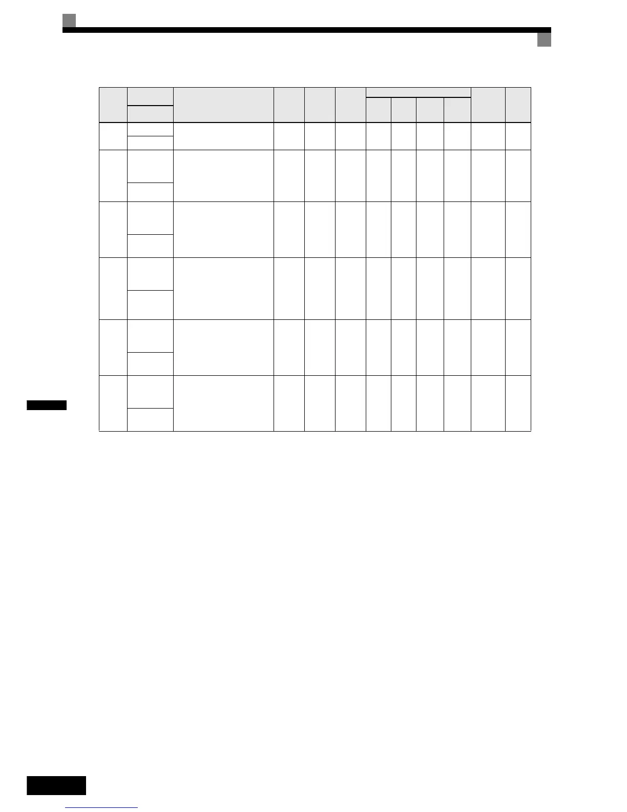
b5-19
PID Setpoint
PID-target value
0 to
100.0%
0NoAAAA1DDH6-99
PID Setpoint
b5-28
PID Square
Root Feed-
back Sel
Enables/Disables the square
root function for the PID feed-
back
0: Disabled
1: Enabled
0 or 1 0 No A A A A 1EAH 6-99
PID Fd SqRt
b5-29
Square root
Feedback
Gain
Sets the gain for the PID
square root feedback function.
0.00 to
2.00
1.00 No A A A A 1EBH 6-99
PID Fd SqRt
Gain
b5-31
PID feed-
back moni-
tor selection
Selects one of the inverters
monitor items (U1-) as
PID feedback signal. The set-
ting number is equal to the
monitor item which has to be
the feedback value.
0 to 18 0 No A A A A 1EDH 6-99
PID Fb Mon
Sel
b5-32
PID monitor
feedback
gain
Sets the gain for the PID feed-
back signal.
0.0 to
1000.0
100.0% No A A A A 1EEH 6-99
PID Fb Mon
Gain
b5-33
PID monitor
feedback
bias
Sets the bias for the PID feed-
back value
-100.0
to
100.0
0.0% No A A A A 1EFH 6-99
PID Fb Mon
Bias
Param-
eter
Num-
ber
Name
Description
Setting
Range
Factory
Setting
Change
during
Opera-
tion
Control Methods
MEMO-
BUS
Register
Page
V/f
V/f
with
PG
Open
Loop
Vector
Closed
Loop
Vector
Display

 Loading...


