5-25
5
Carrier Frequency: C6
Param
eter
Num-
ber
Name
Description
Set-
ting
Range
Fac-
tory
Setting
Change
during
Opera-
tion
Control Methods
MEMO-
BUS
Register
Page
V/f
V/f
with
PG
Open
Loop
Vector
Closed
Loop
Vector
Display
C6-01
Heavy/
Normal
Duty selec-
tion
0: Heavy Duty
1: Normal Duty 1
2: Normal Duty 2
0 to 2 0 No Q Q Q Q 223H
4-5
6-2
Heavy/
Normal
Duty
C6-02
Carrier fre-
quency
selection
Selects the carrier frequency.
Select F to enable detailed settings
using parameters C6-03 to C6-05.
0: Low carrier, low noise
1: 2 kHz
2: 5 kHz
3: 8 kHz
4: 10 kHz
5: 12.5 kHz
6: 15 kHz
F: User setting
0 to F 1 No Q Q Q Q 224H
4-5
4-14
6-2
Carrier
Freq Sel
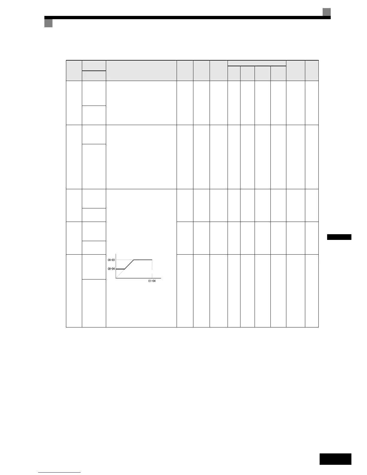
C6-03
Carrier fre-
quency
upper limit
Sets the carrier frequency upper limit
and lower limit in kHz units.
The carrier frequency gain is set as
follows:
In the Open Loop and Closed Loop
Vector control, the upper limit of the
carrier frequency is fixed with C6-
03.
K is a coefficient that depends on the
setting of C6-03.
C6-03 ≥ 10.0 kHz: K = 3
10.0 kHz > C6-03 ≥ 5.0 kHz: K = 2
5.0 kHz > C6-03: K = 1
2.0 to
15.0
* 1
* 2
* 1. The setting range depends on the capacity of the Inverter.
* 2. This parameter can be set only when C6-02 = F.
2.0
kHz
No A A A A 225H 6-2
Carrier
Freq Max
C6-04
Carrier fre-
quency
lower limit
0.4 to
15.0
*1 *2
2.0
kHz
No A A No No 226H 6-2
Carrier
Freq Gain
C6-05
Carrier fre-
quency
propor-
tional gain
00 to
99
*2
00 No A A No No 227H 6-2
Carrier
Freq Sel
Carrier frequency
Output frequency x (C6-05) x
(Max. output frequency)
Output
frequency

 Loading...


