5-71
5
Param-
eter
Num-
ber
Name
Description
Output Signal Level During
Multi-Function Analog Output
Min.
Unit
Control Methods
MEMO-
BUS
Register
V/f
V/f
with
PG
Open
Loop
Vector
Closed
Loop
Vector
Display
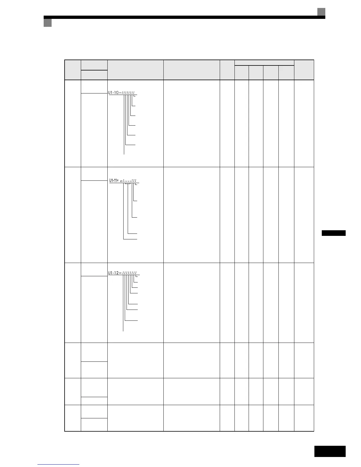
U1-10
Input termi-
nal status
Shows input ON/OFF status.
(Cannot be output.) - Yes Yes Yes Yes 49H
Input Term
Sts
U1-11
Output ter-
minal status
Shows output ON/OFF sta-
tus.
(Cannot be output.) - Yes Yes Yes Yes 4AH
Output Term
Sts
U1-12
Operation
status
Inverter operating status.
(Cannot be output.) - Yes Yes Yes Yes 4BH
Int Ctl Sts 1
U1-13
Cumulative
operation
time
Monitors the total operating
time of the Inverter.
The initial value and the
operating time/power ON
time selection can be set in
o2-07 and o2-08.
(Cannot be output.)
1
hr
Yes Yes Yes Yes 4 CH
Elapsed
Time
U1-14
Software
No. (flash
memory)
(Manufacturer’s ID number) (Cannot be output.) - Yes Yes Yes Yes 4DH
FLASH ID
U1-15
Terminal A1
input level
Monitors the input level of
analog input A1. A value of
100% corresponds to 10V
input.
10 V: 100%
(0 to ± 10 V possible)
0.1% Yes Yes Yes Yes 4EH
Term A1
Level
1: FWD command
(S1) is ON
1: REV command
(S2) is ON
1: Multi input 1
(S3) is ON
1: Multi input 2
(S4) is ON
1: Multi input 3
(S5) is ON
1: Multi input 4
(S6) is ON
1: Multi input 5
(S7) is ON
1: Multi-function
digital output 1
(M1-M2) is ON
1: Multi-function
digital output 2
(M3-M4) is ON
1: Multi-function
digital output 3
(M5-M6) is ON
Not used
(Always 0).
1: Fault output
(MA/MB-MC) is
ON
Run
1: Zero speed
1: Reverse
1: Reset signal
input
1: Speed agree
1: Inverter ready
1: Alarm
1: Fault

 Loading...


