5-72
5
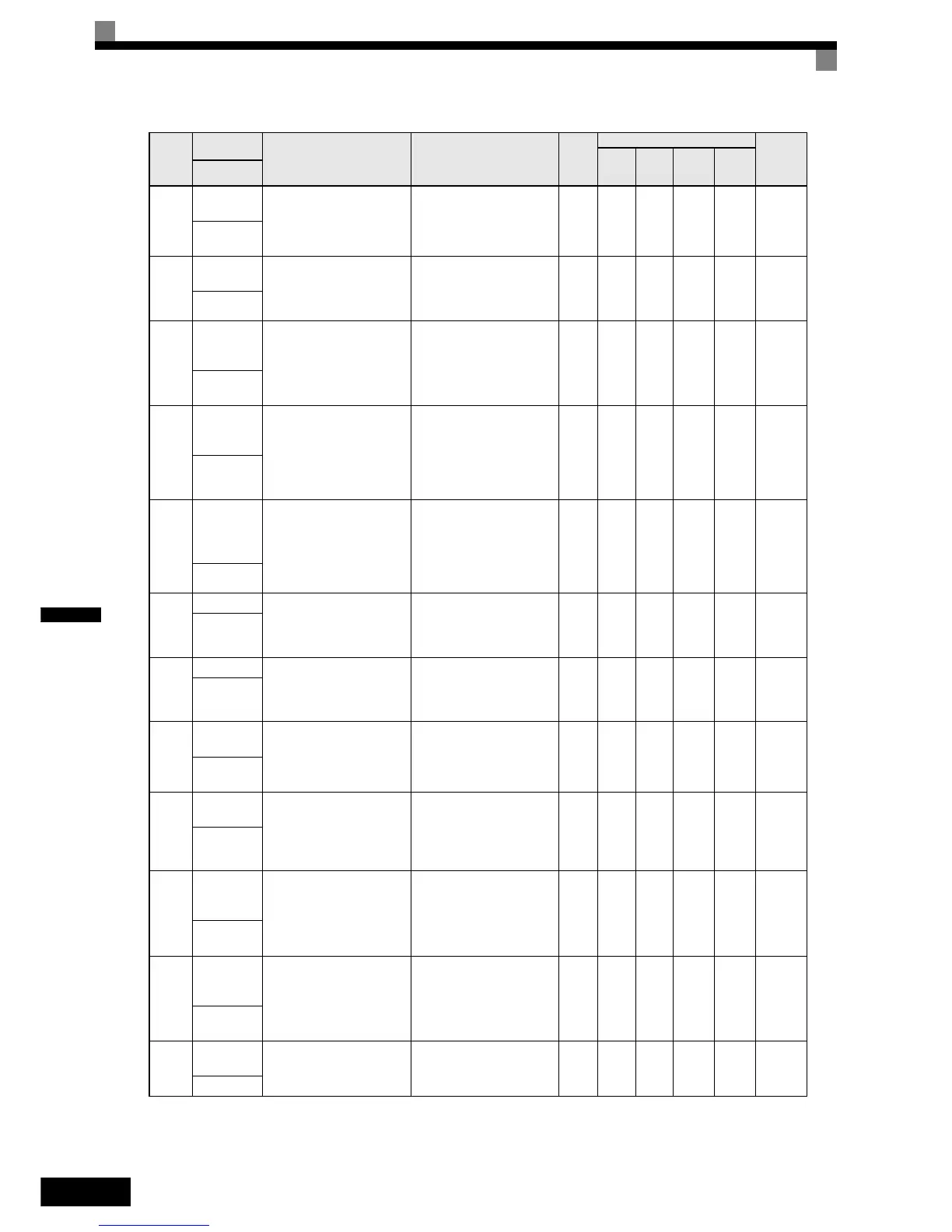
U1-16
Terminal A2
input level
Monitors the input level of
analog input A2. A value of
100% corresponds to 10V/
20mA input.
10 V/20mA: 100%
(0 to ±10 V possible)
0.1% Yes Yes Yes Yes 4FH
Term A2
Level
U1-
17
* 1
Terminal A3
input level
Monitors the input level of
the analog input of AI-14B,
channel 3. A value of 100%
corresponds to 10V.
(Cannot be output.) 0.1% Yes Yes Yes Yes 050H
U1-18
Motor sec-
ondary cur-
rent (Iq)
Monitors the calculated value
of the motor secondary cur-
rent.
The motor rated current cor-
responds to 100%.
10 V:Motor rated current)
(0 to ±10 V output)
0.1% Yes Yes Yes Yes 51H
Mot SEC
Current
U1-19
Motor exci-
tation cur-
rent (Id)
Monitors the calculated value
of the motor excitation cur-
rent.
The motor rated current cor-
responds to 100%.
10 V:Motor rated current)
(0 to ±10 V output)
0.1% No No Yes Yes 52H
Mot EXC
current
U1-20
Frequency
reference
after soft-
starter
Monitors the frequency refer-
ence after the soft starter.
This frequency value does
not include compensations,
such as slip compensation.
The unit is set in o1-03.
10 V: Max. frequency
(0 to ± 10 V possible)
0.01H
z
Yes Yes Yes Yes 53H
SFS Output
U1-21
ASR input Monitors the input to the
speed control loop.
The maximum frequency cor-
responds to 100%.
10 V: Max. frequency
(0 to ± 10 V possible)
0.01
%
No Yes No Yes 54H
ASR Input
U1-22
ASR output Monitors the output from the
speed control loop.
The maximum frequency cor-
responds to 100%.
10 V:Max. frequency
(0 to ± 10 V possible)
0.01
%
No Yes No Yes 55H
ASR output
U1-24
PID feed-
back value
Monitors the feedback value
when PID control is used.
10 V: 100% feedback value
(0 to ± 10 V possible)
0.01
%
Yes Yes Yes Yes 57H
PID
Feedback
U1-25
DI-16H2
Input Status
Monitors the reference value
from a DI-16H2 option card.
The value will be displayed
in binary or BCD depending
on user constant F3-01.
(Cannot be output.) - Yes Yes Yes Yes 58H
DI-16
Reference
U1-26
Output volt-
age refer-
ence (Vq)
Monitors the Inverter internal
voltage reference for motor
secondary current control.
10 V: 200 VAC (400 VAC)
(0 to ± 10 V possible)
0.1 V No No Yes Yes 59H
Voltage
Ref(Vq)
U1-27
Output volt-
age refer-
ence (Vd)
Monitors the Inverter internal
voltage reference for motor
excitation current control.
10 V: 200 VAC (400 VAC)
(0 to ± 10 V possible)
0.1 V No No Yes Yes 5AH
Voltage
Ref(Vd)
U1-28
Software
No. (CPU)
(Manufacturer’s CPU soft-
ware No.)
(Cannot be output.) - Yes Yes Yes Yes 5BH
CPU ID
Param-
eter
Num-
ber
Name
Description
Output Signal Level During
Multi-Function Analog Output
Min.
Unit
Control Methods
MEMO-
BUS
Register
V/f
V/f
with
PG
Open
Loop
Vector
Closed
Loop
Vector
Display

 Loading...


