5-73
5
U1-29
kWH Lower
four digits
Shows the consumed energy
in kWh. U1-29 shoes the
lower four digits, U1-30
shows the upper five digits.
.
U1-30 U1-29
(Cannot be output.)
0.1
kWh
Yes Yes Yes Yes 5 CH
kWh Lower
4 dig
U1-30
kWH Higher
five digits
(Cannot be output.)
1
MW
Yes Yes Yes Yes 5D H
kWh Upper
5 dig
U1-32
ACR output
of q axis
Monitors the current control
output value for the motor
secondary current.
10 V: 100%
(0 to ± 10 V possible)
0.1
%
No No Yes Yes 5FH
ACR(q)
Output
U1-33
ACR output
of d axis
Monitors the current control
output value for the motor
excitation current.
10 V: 100%
(0 to ± 10 V possible)
0.1
%
No No Yes Yes 60H
ACR(d) axis
U1-34
OPE fault
parameter
Shows the first parameter
number when an OPE fault is
detected.
(Cannot be output.) - Yes Yes Yes Yes 61H
OPE
Detected
U1-35
Zero servo
movement
pulses
Shows the number of PG
pulses of the movement range
when zero servo was acti-
vated. The shown value is the
actual pulse number times 4.
(Cannot be output.) - No No No Yes 62H
Zero Servo
Pulse
U1-36
PID input
volume
PID input volume
10 V: 100% PID input
(0 to ± 10 V possible)
0.01
%
Yes Yes Yes Yes 63 H
PID Input
U1-37
PID output
volume
PID control output
10 V: 100% PID output
(0 to ± 10 V possible)
0.01
%
Yes Yes Yes Yes 64 H
PID Output
U1-38 PID setpoint PID set point 10 V: 100% PID set point
0.01
%
Yes Yes Yes Yes 65 H
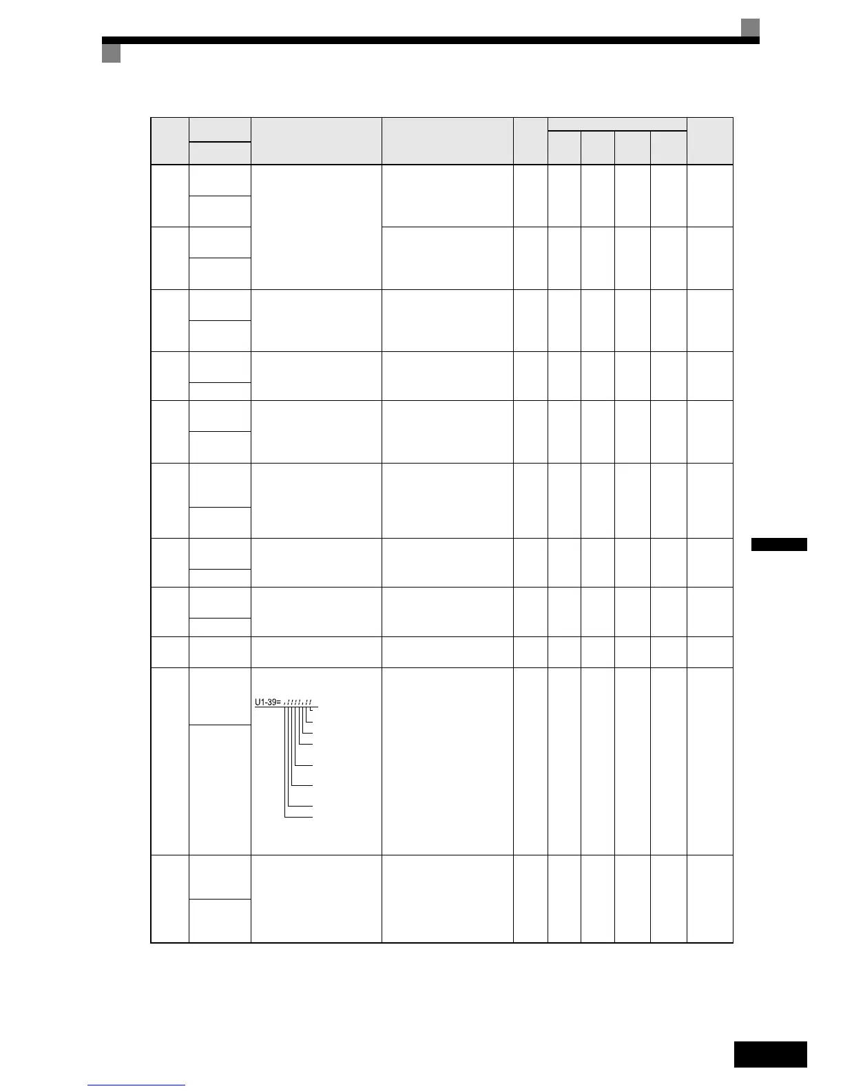
U1-39
MEMOBUS
communica-
tions fault
code
Shows MEMOBUS faults.
(Cannot be output.) - Yes Yes Yes Yes 66H
Transmit Err
U1-40
Cooling fan
operating
time
Monitors the total operating
time of the cooling fan. The
time can be set in
02-10.
(Cannot be output.)
1
hr
Yes Yes Yes Yes 67 H
FAN
Elapsed
Time
Param-
eter
Num-
ber
Name
Description
Output Signal Level During
Multi-Function Analog Output
Min.
Unit
Control Methods
MEMO-
BUS
Register
V/f
V/f
with
PG
Open
Loop
Vector
Closed
Loop
Vector
Display
1: CRC fault
1: Data length fault
Not used
1: Parity fault
1: Overrun fault
1: Framing fault
1: Timeout

 Loading...


