6-42
6
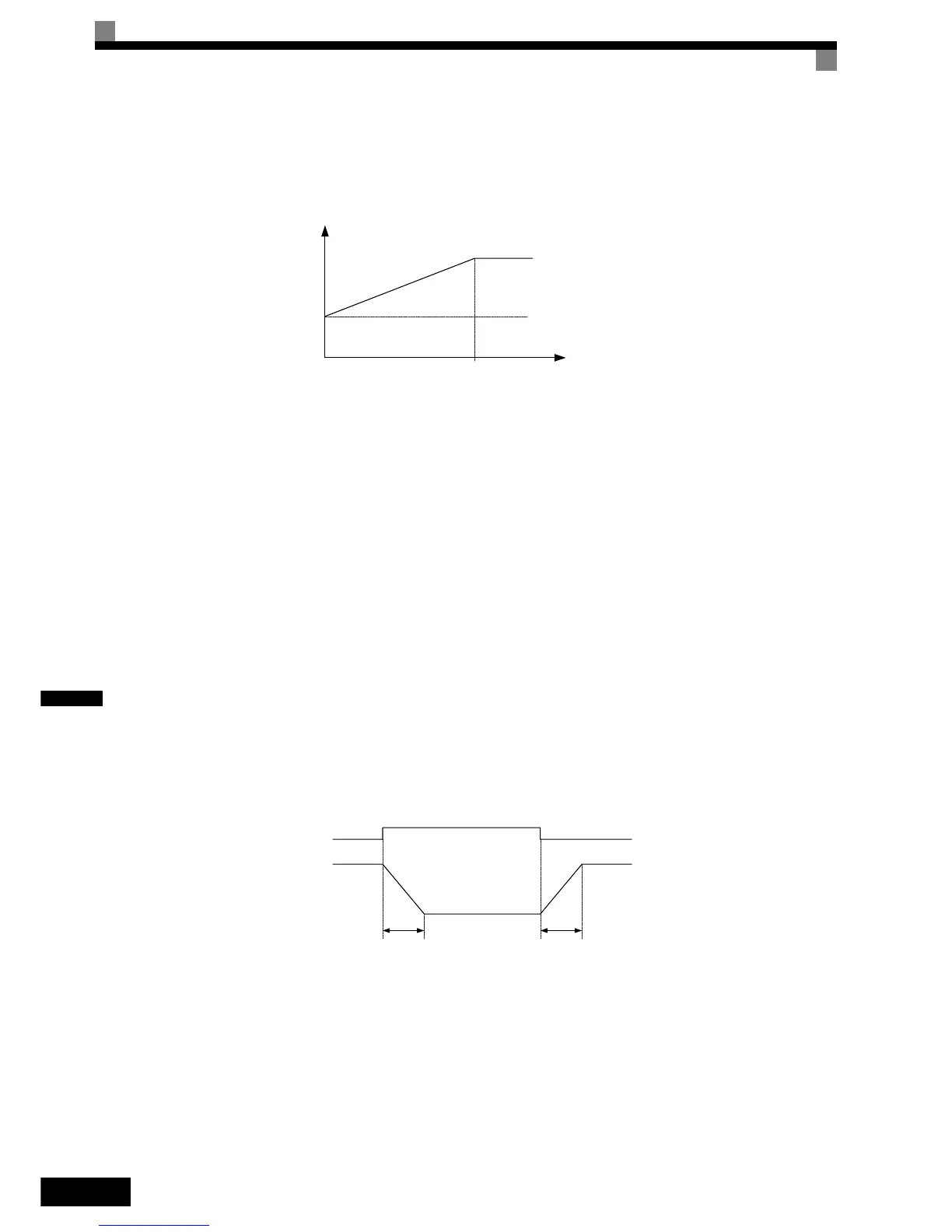
Different Gain Settings for Low-speed and High-speed
Switch between low-speed and high-speed gain when oscillation occurs because of resonance with the
mechanical system at low speed or high speed. The gain and integral time can be switched according to the
motor speed, as shown in Fig 6.44.
Fig 6.44 Low-speed and High-speed Gain Settings
If C5-07 is set to 0, the gain in C5-01 and the integral time in C5-02 are used for the whole speed range.
Setting the Gain Switching Frequency (C5-07)
Set the switching frequency to about 80% of the motor operating frequency or the frequency at which oscilla-
tion occurs.
Low-speed Gain Adjustments (C5-03, C5-04)
Connect the actual load and adjust these parameters at zero-speed. Increase C5-03 (ASR gain 2) and decrease
C5-04 (ASR integral time 2) as long as no oscillation occurs.
High-speed Gain Adjustments (C5-01, C5-02)
Adjust these parameters at normal operating speed. Increase C5-01 (ASR gain 1) and decrease C5-02 (ASR
integral time 1) as long as no oscillation occurs.
ASR Proportional Gain Switch Setting Using a Digital Input
When one of the digital inputs (H1-01 to H1-05) is set to 77, the input can be used to switch between C5-01
(ASR gain 1) and C5-03 (ASR gain 2). ASR gain 1 is used when the multi-function input is OFF, ASR gain 2
is used when the input is ON. This input has higher priority than the ASR switching frequency set in C5-07.
The gain is changed linearly using the integral time 1. See Fig 6.45 for details.
Fig 6.45 ASR Gain Switching by Digital Input
P,I
0
C5-07
P=C5-03
I=C5-04
P=C5-01
I=C5-02
Motor
Speed
ASR gain switch
digital input
ONOFF
C5-02 C5-02
ASR gain C5-01 value
C5-03 value

 Loading...


