6-102
6
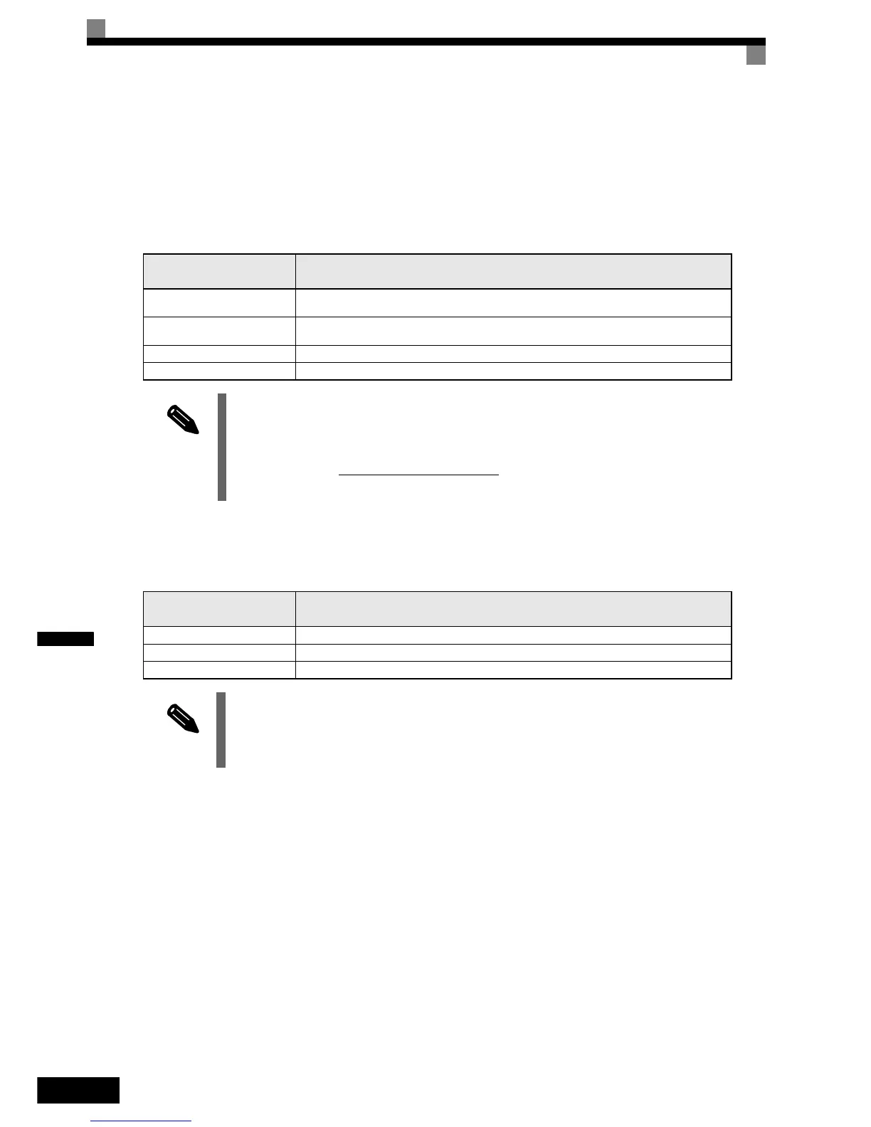
PID Input Methods
PID Target Value Input Sources
Normally, the frequency reference source selected in b1-01 is the PID target value source. If frequency refer-
ence + PID output is selected as PID mode (b5-01=3/4), the PID target value can be set as shown in the fol-
lowing table. Only one input can be selected as PID target input. A duplicate allocation of the PID target
function results in an OPE alarm.
PID Feedback Input Methods
Select one of the following PID control feedback input methods. Only one input can be selected as PID feed-
back input. A duplicate allocation of the PID feedback function results in an OPE error.
PID Target Input Method Setting Conditions
Multi-Function Analog Terminal A2
Input
Set H3-09 to C (PID target value). Either the pulse train input or the analog input A1 can be selected as PID feed-
back value.
MEMOBUS register 0006H
Set MEMOBUS bit 1 in register address 000FH to 1 (enable/disable PID target value from communications) to be
able to use register number 0006H as the PID target value.
Pulse train input Set H6-01 to 2 (PID target value).
Parameter setting If b5-18 is set to 1 the value in b5-19 becomes the PID target value.
INFO
If the PID function is used, the frequency reference value becomes the target value, which is set and
shown in Hz on the operator. Nevertheless, internally the PID target value is used in percent. I.e. the
following formula is used:
Input Method Setting Conditions
Multi-function analog input Set H3-09 (Multi-function Analog Input Terminal A2 Selection) to B (PID feedback).
Pulse train input Set H6-01 to 1 (PID feedback).
Monitor Parameter Set the number of the monitor parameter U1-, which shall be the PID feedback, in parameter b5-31
INFO
Adjust PID target value and PID feedback value using the following items.
• Analog input: Adjust using the analog input terminal gain and bias.
• Pulse train input: Adjust using pulse train scaling, pulse train input gain, and pulse train input bias.
PID target value [%] =
frequency reference [Hz]
max. output frequency [Hz]
• 100%

 Loading...


