6-135
6
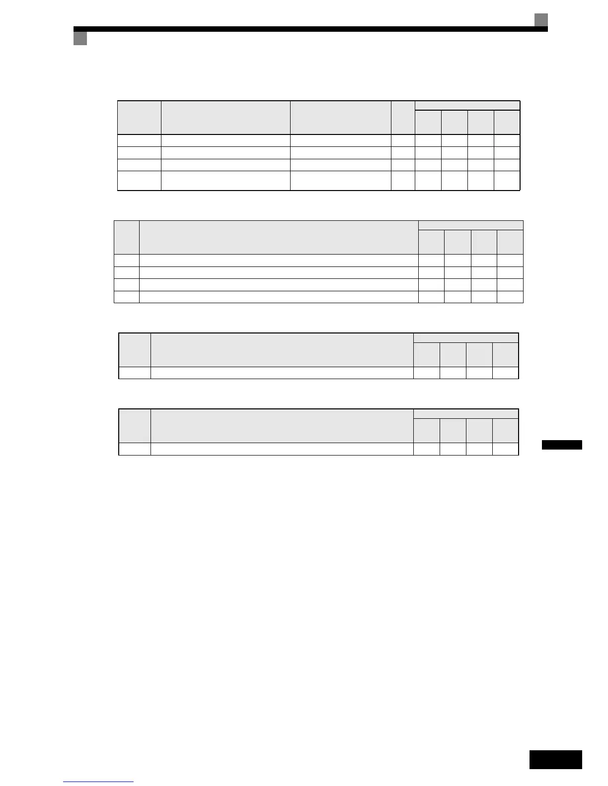
Monitor Items (U1-)
Multi-function Digital Input
Multi-Function Analog Input
Memobus Registers
Setting the Speed Follower Function Mode (S1-01)
Parameter S1-01 enables the Speed Follower Function in following different modes:
• S1-01=1
The drive follows the master encoder speed in both directions (i.e. the master encoder speed is forwarded
to the slave drive with sign).
• S1-01=2
The drive follows the master encoder speed in the forward direction only, it will limit negative reference to
0 Hz.
• S1-01=3
The drive follows the master encoder speed but ignores the master encoder direction (i.e. follows always in
forward direction).
Setting the digital gear ration
In general the digital gear ratio is set by parameters :
The parameters S1-03 to S1-06 specify a fraction the master encoder speed is multiplied with in order to adjust
the slave’s frequency reference.
Parameter
Number
Name
Output Signal Level During
Multi-Function Analog Output
Min.
Unit
Control Methods
V/f
V/f
with
PG
Open
Loop
Vector
Closed
Loop
Vector
U1-85 Master Encoder Reference 10 V: Max. Output Freq. (E1-04) 0.1 Hz A A A A
U1-86 Follower Reference After Gear Ratio 10 V: 100% PID input 0.01% A A A A
U1-87 Gear Ratio Adjustment 10 V: Max. Output Freq. (E1-04) 0.1 Hz A A A A
U1-88
Follower Reference after Gear Ratio Adjust-
ment
10 V: Max. Output Freq. (E1-04) 0.1 Hz A A A A
Set
Value
Function
Control Methods
V/f
V/f
with
PG
Open
Loop
Vector
Closed
Loop
Vector
90 Follower disable Yes Yes Yes Ye s
91 MOP Adjust Increase Yes Yes Yes Ye s
92 MOP Adjust Decrease Yes Yes Yes Yes
93 MOP Adjust Reset Yes Yes Yes Ye s
Set
Value
Function
Control Methods
V/f
V/f
with
PG
Open
loop
Vector
Closed
Loop
Vector
1E Analog Ratio Adjustment (10V = 100.00%) Yes Yes Yes Yes
Memo-
bus
Address
Function
Control Methods
V/f
V/f
with
PG
Open
loop
Vector
Closed
Loop
Vector
72AH Communication Gear Ratio Adjustment (1 = 0.01%) Yes Yes Yes Yes
Gear Ratio
S1-03 10000×()S1-05+
S1-04 10000×()S1-06+
--------------------------------------------------------------=

 Loading...


