6-151
6
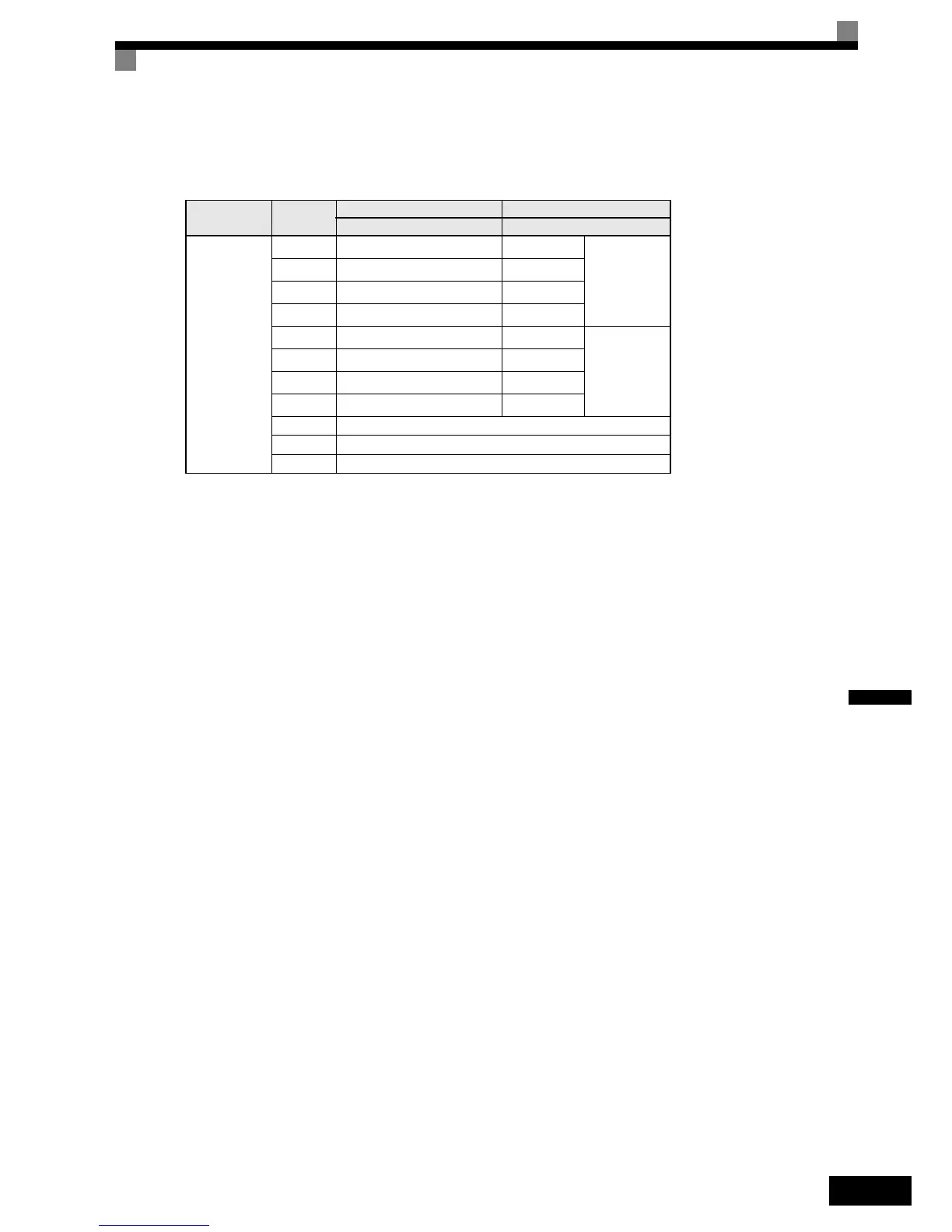
Selecting the Input Terminal Function for a DI-08 Digital Reference Card
The frequency reference from a DI-08 Card is determined by the setting of F3-01, as shown in the following
table.
Application Precautions
The DI-08 will not function if F3-01 is set to 6.
Terminal Pin No.
8-bit Binary with Sign 2-digit BCD with Sign
F3-01 = 7 F3-01 = 0 to 5
TC
1
Bit 0 (2
0
)
1
BDC digit 1
(0 to 9)
2
Bit 1 (2
1
)
2
3
Bit 2 (2
2
)
4
4
Bit 3 (2
3
)
8
5
Bit 4 (2
4
)
1
BDC digit 2
(0 to 15)
6
Bit 5 (2
5
)
2
7
Bit 6 (2
6
)
4
8
Bit 7 (2
7
)
8
9 Sign signal
10 SET (read) signal
11 Reference common signal (0 V)

 Loading...


