2-10
2
* The wire thickness is set for copper wires at 75°C.
F7Z4185
R/L1, S/L2, T/L3
M16 78.4 to 98
95 to 300
(4/0 to 600)
150 × 2P
(300 × 2P)
Power cables,
e.g., 600 V vinyl
power cables
U/T1, V/T2, W/T3, R1/L11, S1/L21, T1/L33
120 × 2P
(250 × 2P)
, 1
300 × 2P
(600 × 2P)
3
–
95 × 2P
(3/0 × 2P
r/l1, Δ200/
l2
200, Δ400/
l2
400
M4 1.3 to 1.4
0.5 to 4
(20 to 10)
1.5
(16)
F7Z4220
R/L1, S/L2, T/L3
M16 78.4 to 98
95 to 300
(4/0 to 600)
240 × 2P
(500 × 2P)
U/T1, V/T2, W/T3, R1/L11, S1/L21, T1/L33
240 × 2P
(400 × 2P)
, 1
120 × 4P
(250 × 4P)
3
–
120 × 2P
(250 × 2P)
r/l1, Δ200/
l2
200, Δ400/
l2
400
M4 1.3 to 1.4
0.5 to 4
(20 to 10)
1.5
(16)
F7Z4300
R/L1, S/L2, T/L3
M16 78.4 to 98
95 to 300
(4/0 to 600)
120 × 4P
(250 × 4P)
R1/L11, S1/L21, T1/L31
U/T1, V/T2, W/T3
120 × 4P
(4/0 × 4P)
, 1
240 × 4P
(400 × 4P)
3
–
120 × 2P
(250 × 2P
r/l1, Δ200/
l2
200, Δ400/
l2
400
M4 1.3 to 1.4
0.5 to 4
(20 to 10)
1.5
(16)
IMPORTANT
Determine the wire size for the main circuit so that line voltage drop is within 2% of the rated voltage.
Line voltage drop is calculated as follows:
Line voltage drop (V) =
x wire resistance (W/km) x wire length (m) x current (A) x 10
-3
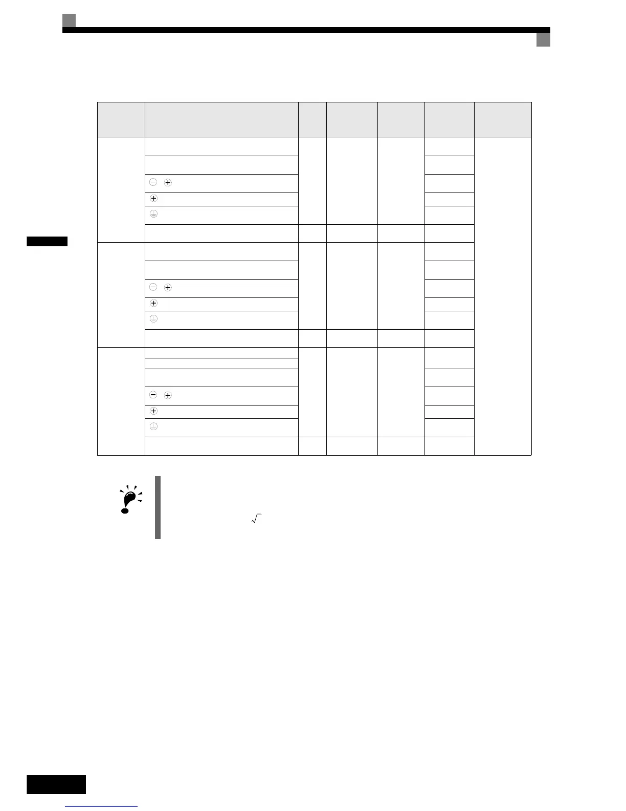
Table 2.2 400 V Class Wire Sizes
Inverter
Model
CIMR-
Terminal Symbol
Termi-
nal
Screws
Tightening
Torque
(N•m)
Possible
Wire Sizes
mm
2
(AWG)
Recom-
mended Wire
Size mm
2
(AWG)
Wire Type
3

 Loading...


