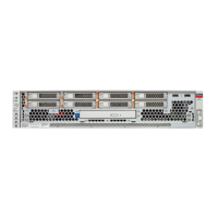
Server Block Diagram
No. Component Oracle ILOM Target Links
2 PS backplane and cover
/SYS/PDB
“Servicing the PS
Backplane” on page 165
3 Fan board
/SYS/FANBD
“Servicing the Fan
Board” on page 137
4 Fan modules
/SYS/FANBD/F0
/SYS/FANBD/F1
/SYS/FANBD/F2
“Servicing Fan
Modules” on page 75
Server Block Diagram
This block diagram shows the connections between and among components and device slots
on the server. Use this block diagram to determine the optimum locations for optional cards or
other peripherals, based on your server's configuration and intended use.
Note - For more detail on root complexes related to the PCIe slots, see “I/O Root Complex
Connections” on page 121.
Identifying Components 23
 Loading...
