ZS3-4 Controller Hardware Overview
ZS3-4 Internal Boards - The ZS3-4 controller chassis contains the following field-replaceable
units (FRUs). FRUs are not customer-serviceable, and should only be replaced by trained
Oracle service technicians.
■
Motherboard - The motherboard includes CPU modules, slots for eight DIMM risers,
memory control subsystems, and the service processor (SP) subsystem. The SP subsystem
controls the host power and monitors host system events (power and environmental). The
SP controller draws power from the host's 3.3V standby supply rail, which is available
whenever the system is receiving AC input power, even when the system is turned off.
■
Power Distribution Board - The power distribution board distributes main 12V power
from the power supplies to the rest of the system. It is directly connected to the Vertical
PDB card, and to the motherboard through a bus bar and ribbon cable. It also supports a top
cover interlock ("kill") switch. In the controller, the power supplies connect to the power
supply backplane which connects to the power distribution board.
■
Vertical PDB Card - The vertical power distribution board, or Paddle Card serves as the
interconnect between the power distribution board and the fan power boards, hard drive
backplane, and I/O board.
■
Power Supply Backplane Card - This board connects the power distribution board to
power supplies 0 and 1.
■
Fan Power Boards - The two fan power boards are FRUs and carry power to the controller
fan modules. In addition, they contain fan module status LEDs and transfer I2C data for the
fan modules.
■
Drive Backplane - The six-drive backplane includes the connectors for the drives, as well
as the interconnect for the I/O board, Power and Locator buttons, and system/component
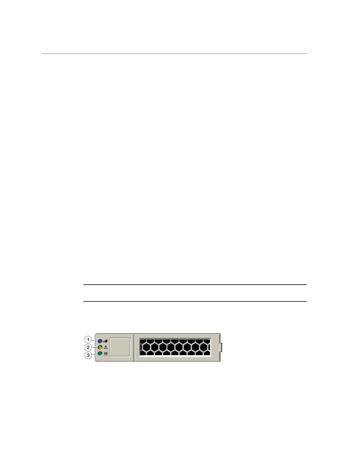
status LEDs. Each drive has an LED indicator for Power/Activity, Fault, and Locate.
ZS3-4 System Drives - The ZS3-4 controller has two system boot drives in slots 0 and 1,
configured as a mirrored pair. Read-optimized cache devices can be installed in controller slots
2 through 5, or installed in DE2 disk shelf slots.
Note - Read cache devices cannot be installed in both controller and disk shelf slots at the same
time. (See DE2 Disk Shelf Front Panel for software requirements and slot configuration rules.
FIGURE 18
ZS3-4 Controller System Drive
Servicing the ZS3-4 Controller 117

 Loading...


