3-6-2. COARSE ADJUSTMENT OF THE
TAPE
GUIDE POST HEIGHTS
(P2 and P3)
Note: The Tape Guide Posts have been precisely
adjusted at the factory. Therefore, normally
do not change the height of the
P2
and
P3
Posts.
To prevent the alignment tape from being
damaged, use a
normal cassette tape for this
procedure.
«TOOL»
Post Adjustment Plate
Reel Table
Height Gauge
Post Adjustment Screwdriver;
Check Light
L Type Screwdriver
VFK0191
VFK0190
VFK0329
VFK0948
VFK0269
1.
Remove the cassette compartment (Refer to
Disassembly Procedures).
2.
Place the Post Adjustment Plate over the reel
tables.
Confirm that the Post Adjustment Plate is
firmly seated
as
shown
in
Figure M25-A.
P2
P3
VFK0191
Figure M25-A
3. Lower 2 tape guide posts (P2 and
P3)
by turning
the
Post Adjustment screwdriver
so
that the
condition of post becomes
as
shown
in
Figure
M25-B. That
is
the lower edge of Tape guide
should
be
lower than surface of Adjustment Plate.
HEIGHT GAUGE
SCRAPER
VFK0191
LOCK
SCREW
~.-L-----"'---o"T'
Figure M25-B
Note: Before turning
P2
and
P3
slightly loosen the
Lock
Screw using the L Type Screwdriver.
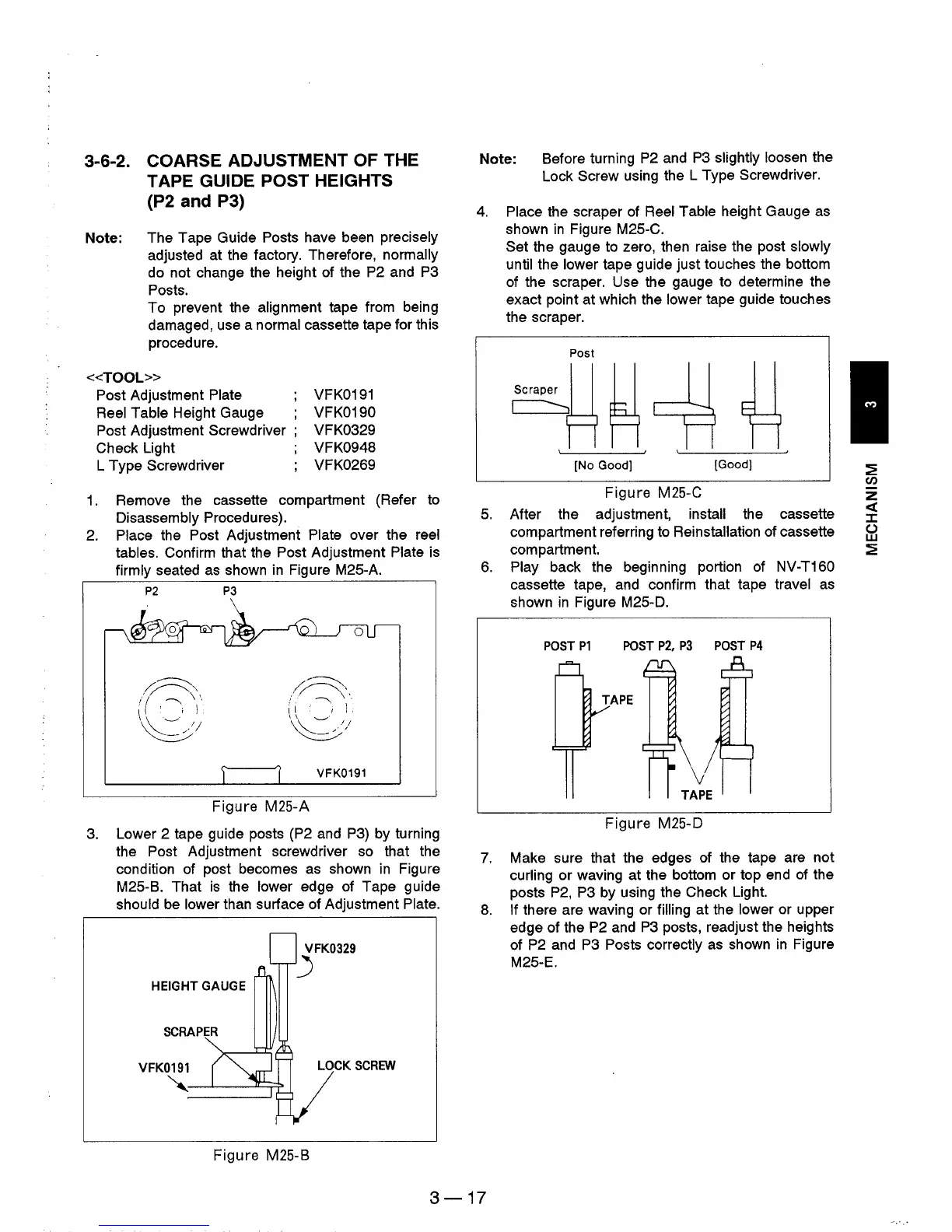
4.
Place the scraper
of
Reel Table height Gauge
as
shown
in
Figure M25-C.
5.
6.
Set the gauge to zero, then raise the post slowly
until
the lower tape guide just touches the bottom
of the scraper. Use the gauge to determine the
exact point at which the
lower tape guide touches
the scraper.
Post
[No Good]
[Good)
Figure M25-C
After the adjustment, install the cassette
compartment referring to
Reinstallation of cassette
compartment.
Play back the beginning portion
of
NV-T160
cassette tape, and confirm that tape travel
as
shown
in
Figure M25-D.
POST
P1
POST
P2,
P3
POST
P4
Figure M25-D
7.
Make sure that the edges of the tape are not
curling or waving at the bottom or top end
of
the
posts
P2,
P3 by using the Check Light.
8.
If there are waving or filling at the lower or upper
edge of the
P2
and
P3
posts, readjust the heights
of
P2
and
P3
Posts correctly
as
shown
in
Figure
M25-E.
3-17
:2
(/)
z
«
J:
()
w
:2