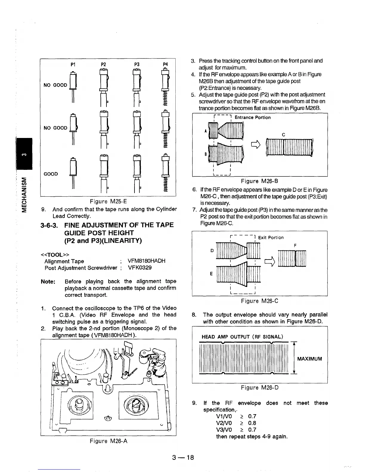
P1
P2
P3
P4
NO
GOOD
~
NO GOOD
~
GOOD
~
Figure
M25-E
9.
And confirm that the tape runs along the Cylinder
Lead Correctly.
3-6-3. FINE ADJUSTMENT OF THE TAPE
GUIDE POST HEIGHT
(P2 and P3)(UNEARITY)
«TOOL»
Alignment Tape
Post Adjustment Screwdriver ;
VFM8180HADH
VFK0329
Note:
Before playing back the alignment tape
playback a normal cassette tape and confirm
correct transport.
1.
Connect the oscilloscope to the
TP6
of the Video
1 C.B.A. (Video RF Envelope and the head
switching
pulse as a triggering signal.
2. Play back the 2-nd portion (Monoscope 2) of the
alignment tape (VFM8180HADH).
Figure
M26-A
3.
Press the tracking control button
on
the front
panel
and
adjust for maximum.
4.
If
the
RF
envelope
appears
like
example
A
or
B
in
Rgure
M26B then adjustment of the tape
guide
post
(P2:Entrance) is necessary.
5. Adjust the tape guide post
(P2)
with
the post adjustment
screwdriver so that the
RF
envelope wavefrom at the
en
trance portion becomes flat
as
shown
in
Figure M26B.
r - -
-,
Entrance Portion
I I
I I
I I
L
___
.J
Figure
M26-B
6.
If the RF envelope appears
like
example D or E
in
Figure
M26-C , then adjustment of the tape guide post
(P3:Exit)
is
necessary.
7.
Adjust the tape guide post
(P3)
in
the same manner as the
P2
post
so
that the exit portion becomes flat
as
shown
in
Figure M26-C.
r - - -
-1
Exit Portion
o
1111111'IIMffil
r-1\
IJlIF
E"~
I I
L
____
.J
Figure
M26-C
8.
The
output envelope should vary nearly parallel
with other condition as shown in Figure M26-D.
HEAD
AMP
OUTPUT
(RF
SIGNAL)
..
...--
IMAXIMUM
~
__
~n
~
Figure
M26-D
9.
If the RF envelope does not meet these
specification
"
V1/V0
~
0.7
V2/V0
~
0.8
V3/V0
~
0.7
then repeat steps 4-9 again.
3-18