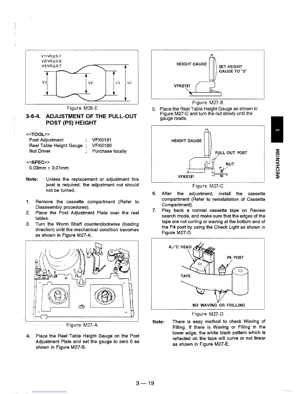
V1IVO~O.7
V2IVO~O.8
V3IVO~O.7
V1
V2
V3
VO
Figure M26-E
3-6-4. ADJUSTMENT OF THE PULL-OUT
POST
(PS)
HEIGHT
«TOOL»
Post Adjustment
Reel Table Height Gauge
Nut Driver
«SPEC»
0.03mm ±
0.01
mm
VFK0191
VFK0190
Purchase locally
Note: Unless the replacement or adjustment this
post is required, the adjustment nut
should
not
be
turned.
1.
Remove the cassette compartment (Refer to
Disassembly procedures).
2.
Place the Post Adjustment Plate over the reel
tables.
3.
Turn the Worm Shaft counterclockwise (loading
direction)
until the mechanical condition becomes
as
shown
in
Figure M27-A.
Figure M27-A
4.
Place the Reel Table Height Gauge
on
the Post
Adjustment Plate and set the gauge to zero 0 as
shown
in
Figure M27-B.
HEIGHT GAUGE
SET
HEIGHT
GAUGE
TO
·0·
VFK0191 (
ot
" l
Figure M27-B
5.
P!ace the Reel Table Height Gauge
as
shown
in
Figure M27-C and turn the nut slowly until
the
gauge reads.
HEIGHT GAUGE
P
LL
OUT
POST
Figure M27-C
6. After the adjustment, install the cassette
compartment (Refer to
reinstallation of Cassette
Compartment) .
7.
Play back a normal cassette tape
on
Review
search mode, and make sure that the edges
of
the
tape are not
curling or waving at the bottom end of
the
P4 post by using the Check Light
as
shown
in
Figure M27-D.
P4
POST
NO
WAVING
OR
FRILLlNG
Figure M27-D
Note: There
is
easy method to check Waving
of
Filling. If there is Waving or Filling
in
the
lower edge, the white black pattern which
is
reflected
on
the tape will curve or not linear
as
shown
in
Figure M27-E.
3-19
:2
en
z
«
::z::
()
w
:2