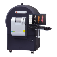
Quantum GX2 microCT Imaging System Manual Chapter 6 | Image Acquisition 56
3. In the Xcapture window, adjust the ROI dimensions to position it over the apex of the heart and
diaphragm.
4. Rotate the gantry 90 degrees. Ensure that the subject is within the filed of view and the ROI is
correctly positioned.
5. Rotate the gantry back to 0 degree position.
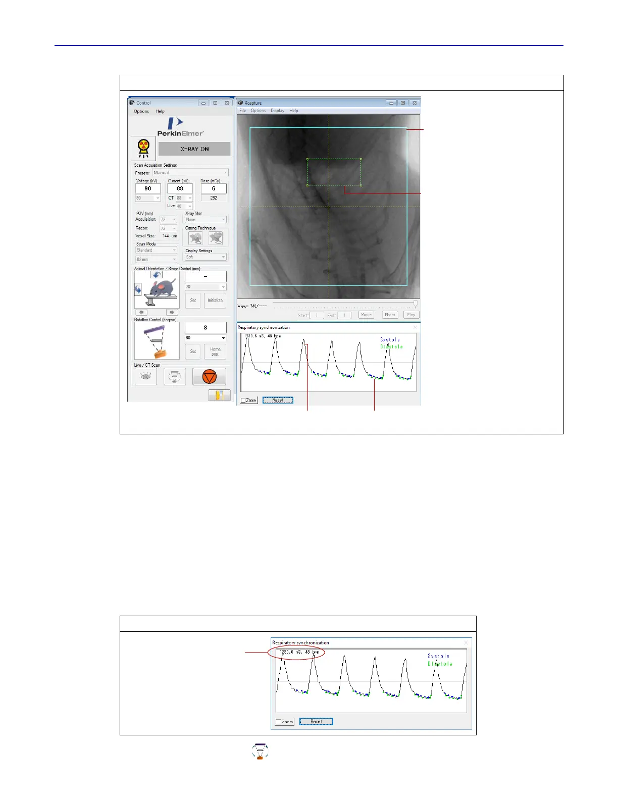
6. Check the respiratory and cardiac signal trace in the Respiratory synchronization window
(Figure 6.21).
The large trace spikes represent diaphragm movement. The smaller spikes in between represent
cardiac movement. Ensure that the cardiac signal is as visible as possible (Figure 6.21). It may
be possible to improve the signal visibility by adjusting the ROI position.
Wait for the breath rate to stabilize with longer than 1000 ms ±1 sec between breaths.
7. Click the CT Scan button to begin the scan.
Figure 6.20 Xcapture Window
Figure 6.21 Respiratory Synchronization
Image data bounding box
Image data outside the
bounding box are not
used in the
reconstruction.
Position the ROI over
the apex of the heart
and diaphragm
Diaphragm motion signals Cardiac motion signals
Time between breaths (ms)
and breaths per minute (bpm)
 Loading...