Home
PESA
Controller
Cheetah PERC2000
Page 110 (Figure 8-63 Update Mode Display)
PESA Cheetah PERC2000 - Figure 8-63 Update Mode Display; Figure 8-64 Online Update Bar; Figure 8-65 Online Updated
124 pages
Manual
Save Page as PDF
To Next Page
To Next Page
To Previous Page
To Previous Page
Loading...
User
Gu
i
de – PERC2
000 Sys
tem Co
ntroller
Publication 81
-9059
-0605
-0, Rev. B
November 20
10
Proprietary Infor
mation
of
PESA
PESA
8-64
Figu
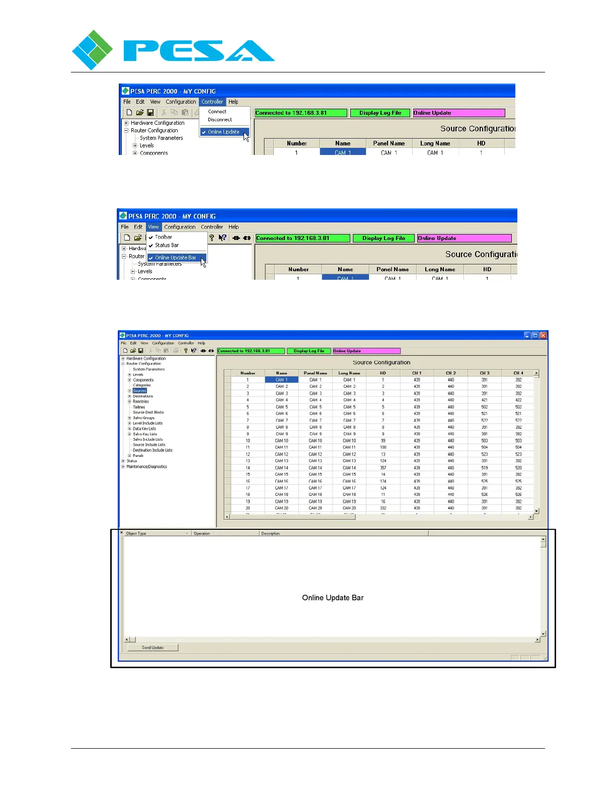
re 8-63
Upd
a
te Mode Display
Figu
re 8-64
On
line Upda
te B
a
r Menu
Entry
Figu
re 8-65
On
line Upda
te Display Window
109
111
Table of Contents
Main Page
Default Chapter
3
Table of Contents
3
Chapter 1 About this Manual
8
Documentation and Safety Overview
8
Cautions , and Notes
8
Caution
8
Note
8
I Nstallation
8
End User Commercial License Agreement
9
Grant
9
Limited Warranty
9
Scope of Grant
10
You May
10
You May Not
10
Title
10
Termination
10
Miscellaneous
11
Chapter 2 - Introduction
12
Product Description
12
Perc2000 System Controller Circuit Card
12
Controller System Communication Protocols
13
Perc2000 Installation Options
14
Figure 2-2 Typical Perc2000 System Controller Installation
14
Figure 2-3 Typical Video Router Frame Installation
15
Figure 2-4 Stand-Alone Chassis Installation
15
Features
16
Operational Environment
17
Chapter 3 - Installation
18
Introduction
18
Shipping Damage Inspection
18
Unpacking
18
Installing Stand -Alone Perc2K-Sor Perc2K-D Controller
18
Figure 3-1 Stand-Alone Chassis Front View
19
Figure 3-2 Stand-Alone Chassis Rear View
19
Figure 3-3 Typical Video Router Installation
20
Perc2000 External I/O Connections
21
Figure 3-4 Typical Video Frame Connector Panel
21
Figure 3-6 Rs-232 Cpu Link (Null Modem ) Cable
22
L D E F
22
Com 4) C Onnectors
22
COM 3/PRC Bus (Index 2)
23
Figure 3-7 Rs-232 Cpu Link (at Serial Modem ) Cable
23
Figure 3-8 Rs-422 Cpu Link Cable
23
Figure 3-10 Rs-422 Serial Cable for Prc Bus
24
Figure 3-11 5-Pin Connector Pin-Out
24
Figure 3-12 Rs-422 System Expansion Cable
24
Figure 3-13 Ethernet Connector
25
Network Connectors (Index 3)
25
Pin-Out Diagram
26
F Abrication
27
Figure 3-15 Rs-485 Serial Cable Wiring for Rcp Bus
27
Chapter 4 Installing Perc2000 Software
28
Description
28
Perc2000 Gui Installation
28
Chapter 5 Initial System Operation
33
Gui Application Network Configuration
33
Network Addressing
34
Changing Initial Network Parameters
34
Networked Host Pc and System Controller
35
Figure 5-2 System Controllers Configuration Screen
36
Changing the Base Ip Address of Aperc2000 System Controller Module
37
Figure 5-3 "IP Config" Utility Command Location and Select Device Window
38
Dual (Redundant ) P2K System Controllers
39
Chapter 6 - P2K Hardware Description
40
Ntroduction
40
Perc2000 System Controller Circuit Card Assembly
40
Card Edge Controls and Indicators
42
Reset
42
Power (PWR) in
42
Regulators (REGS) OK
42
Alarm
42
Active
42
ETHERNET Leds
43
Sp Led
43
USB Connector
43
Stand -Alone Chassis Frame Assembly
43
Figure 6-3 Stand -Alone Frame
43
Circuit Card Removal and Installation
44
Power Supply Module
44
Power Supply Module Removal and Installation
45
Chapter 7 - Maintenance and Repair
46
Periodic Maintenance
46
Pesa Customer Service
46
Repair
46
Replacement Parts
46
Factory Service
46
Chapter 8 - Perc 2000 Operating Software
47
Introduction
47
Hardware Configuration and Router Configuration
47
Navigating the Perc2000 System Screen
48
Common Right Mouse Click Functions
50
Copy, Cut, Paste, Delete
50
Quick Data Entry Tools
50
Figure 8-2 Typical Right -Click
50
Figure 8-3 Copy and Increment
51
Figure 8-4 Copy and Increment
51
Figure 8-5 Auto Incrementf
52
Figure 8-6 Auto Incrementb
52
Figure 8-7 Fill-Down Command
53
Figure 8-8 Fill-Up Command
53
Figure 8-9 Fill-Right
53
Getting Started
54
Figure 8-10 Fill -Left
54
Establish Communication with the System Controller Card
55
Figure 8-11 System Controller
55
Hardware Configuration Commands
56
Perc2000 System Controller Configuration Files
56
Figure 8-12 Hardwarec
56
Router Configuration Commands
57
System Parameters
57
Figure 8-13 Router Configuration
57
Figure 8-14 System Parameters
58
Figure 8-15 Status Filters
61
Levels Configuration
62
Figure 8-16
62
Figure 8-17 Levels Configuration
63
Figure 8-18 Levels Configuration
63
Components Configuration
65
Figure 8-19 Right Mouse Click
65
Figure 8-20 Components of
65
Figure 8-21 Componentsc
67
Figure 8-22 Componentsc
67
Categories
69
Figure 8-23 Right Mouse Click
69
Figure 8-24 Categoriesc
69
Figure 8-25 Right Mouse Click
70
Sources
71
Figure 8-26 Sources Configuration
71
Figure 8-27 Right Click Mouse
73
Figure 8-28 Source Range Entry
74
Figure 8-29 Sources Spreadsheet
75
Destinations
76
Figure 8-30 Tieline Configuration
76
Figure 8-31 Destinationsc
77
Figure 8-32 Right Click Mouse
78
Figure 8-33 Destination Range
79
Figure 8-34 Destinations
80
Reentries Configuration Screen
81
Figure 8-35 Sync Referencea
81
Figure 8-36 Reentry Example
81
Onfiguration Screen
81
Figure 8-37 Reentry Configuration
82
Figure 8-38 Adding or Deleting a
83
Tie-Lines Configuration Screen
83
Figure 8-39 Tie -Line Configuration
84
Source-Destination (Dest) Blocks Configuration Screen
85
Onfiguration Creen
85
Figure 8-40 Source -Destination
86
Configuration Screen
86
Salvo Groups Configuration Screen
87
Figure 8-42 Salvo Groupc
87
Figure 8-43 Right Mouse Click
88
Level Include Lists Configuration Screen
89
Figure 8-44 Level Include Lists
89
Ists Configuration Screen
89
Ists Onfiguration Creen
89
Figure 8-45 Level Include List
90
Data Key Lists Configuration Screen
91
Figure 8-46 Data Key Listsc
91
Figure 8-47 Data Key Lists Data
92
Figure 8-48 Data Functiona
93
Salvo Key Lists Configuration Screen
94
Figure 8-49 Salvo Key Listsc
95
Figure 8-50 Salvo Key Listsd
96
Figure 8-51 Salvo Key Listsd
97
Figure 8-52 Salvo Include Lists
98
Salvo Include Lists Configuration Screen
98
Figure 8-53 Source Includel
99
Source Include Lists Configuration Screen
99
Destination Include Lists Configuration Screen
100
Figure 8-54 Source Includel
100
Figure 8-55 Destination Include
101
Figure 8-56 Destination Include
102
Panels Configuration Screen
102
Figure 8-57 Panels Configuration
103
Figure 8-58 Addinga Panelc
104
Figure 8-59 Panels Configuration
104
Figure 8-60 Panel Operational
106
Incremental Add /Edit (O N -Line Update )
108
Configuration Update Modes
108
Figure 8-61 Assigned Panell
108
Using Online Update Mode
109
Figure 8-62 Update Statusw
109
Figure 8-63 Update Mode Display
110
Figure 8-64 Online Update Bar
110
Figure 8-65 Online Updated
110
Figure 8-66 Online Update Data
112
Status Commands
113
Matrix Status
114
Figure 8-67 Status Commands
114
Matrix Preset
115
Figure 8-68 Matrix Statusd
115
Figure 8-69 Matrix Presetd
116
Panel Status
117
Figure 8-70 Panel Status Display
117
Salvo Status
118
Figure 8-71 Salvo Status Display
118
Menu Bar
119
File Menu
119
Figure 8-72 File Menu
119
Edit Menu
120
Figure 8-73 Edit Menu
120
View Menu
121
Configuration Menu
121
Controller Menu
121
Figure 8-74 View Menu
121
Figure 8-75 Controller Menu
121
Help Menu
122
Figure
122
Figure 8-77 Flash Utility Menu
123