User Guide – PERC2000 System Controller
Publication 81-9059-0605-0, Rev. B
November 2010
Proprietary Information of
PESA 3-6
DSR (Data Set Ready)
RTS (Ready To Send)
CTS (Clear To Send)
DTR (Data Terminal Ready)
DB-9 Female To:
3500Plus-S J13 or J14
3TX (Transmit Data)
SG (Signal Ground)
RI (Ring Indicator)
5
6
7
8
9
4
CD (Carrier Detect)
RX (Receive Data)
1
2
RI (Ring Indicator)
RTS (Ready To Send)
CTS (Clear To Send)
DTR (Data Terminal Ready)
SG (Signal Ground)
DSR (Data Set Ready)
RX (Receive Data)
TX (Transmit Data)
CD (Carrier Detect)
2
6
7
4
5
22
20
DB-25 Male To:
External Modem
8
3
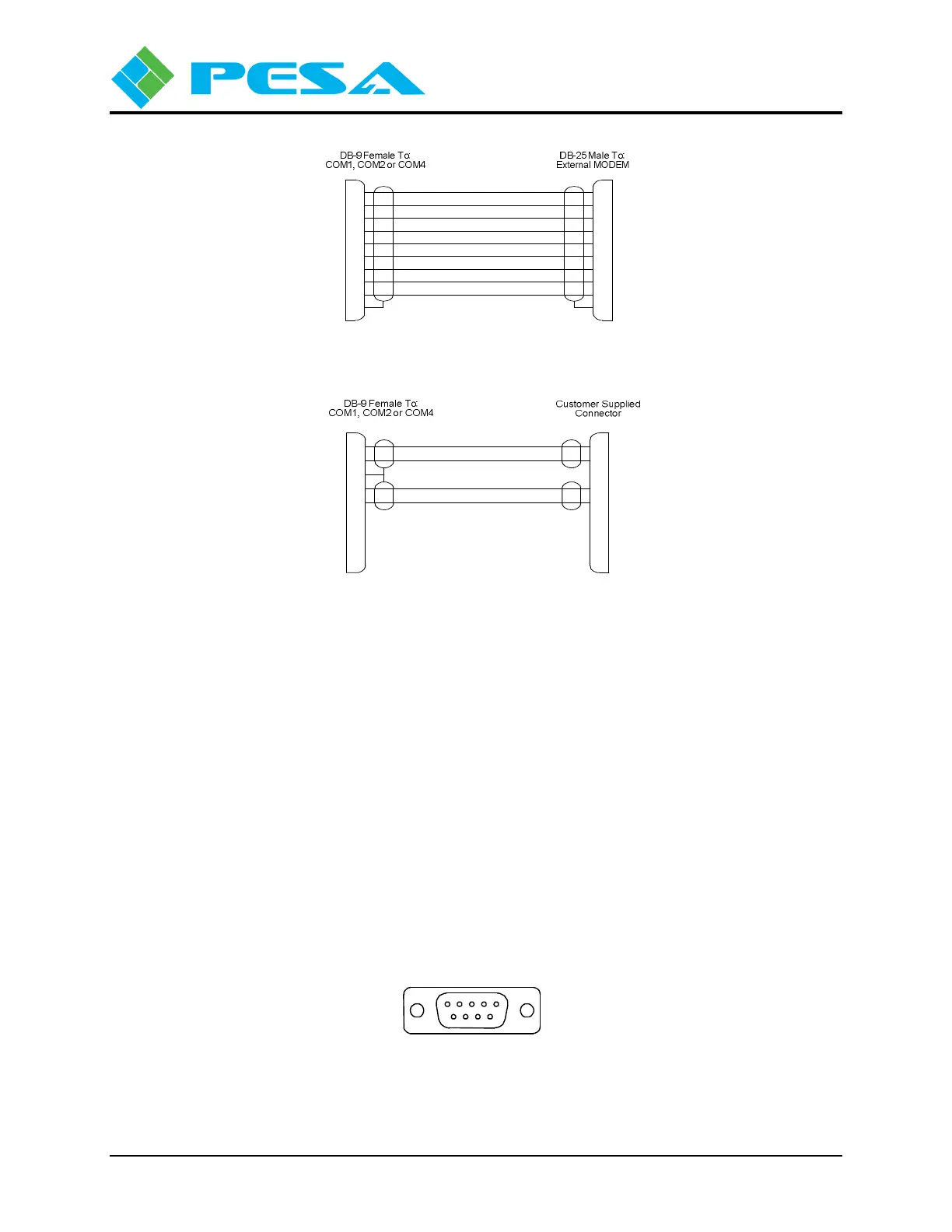
Figure 3-7: RS-232 CPU Link (AT Serial Modem) Cable
System Controller RX- (Low)
System Controller RX+ (High)
System Controller TX- (Low)
System Controller TX+ (High)
6Chassis Ground
Chassis Ground 9
DB-9 Female To:
3500Plus-S J6
System Controller RX+ (High)
System Controller RX- (Low)
System Controller TX- (Low)
System Controller TX+ (High)
Chassis Ground
Chassis Ground
Chassis Ground
2
7
8
3
4
5
1
Customer supplied
Connector
Figure 3-8: RS-422 CPU Link Cable
3.6.2 COM
3/PRC
B
US
(I
NDEX
2)
Serial port COM 3 is the system control communications interface with other PESA routing
switchers within the facility using the PESA Router Control (PRC) protocol, and is connected
between PESA PRC-compatible routers using an RS-422 serial control cable. The COMM 3 port
is unique in that it has a 5-pin connector wired in parallel with the DB9. In most applications the
5-pin connectors on all system frames are interconnected in a daisy-chain fashion. The DB9
(COMM 3) connector is also active, if you wish to use it. Note that the 5-pin connector scheme is
a legacy from previous PESA controller systems.
When using the DB9 RS-422 serial bus connector, you may obtain cables from PESA or fabricate
your own, using the connector pin diagram shown by Figure 3-9 and pin-out diagram provided by
Figure 3-10.
Contact locations when viewed
from rear of chassis.
6 7 8 9
1 2 3 4 5
Figure 3-9: COM 3/PRC Connector


 To Next Page