User Guide – PERC2000 System Controller
Publication 81-9059-0605-0, Rev. B
November 2010
Proprietary Information of
PESA PESA 8-30
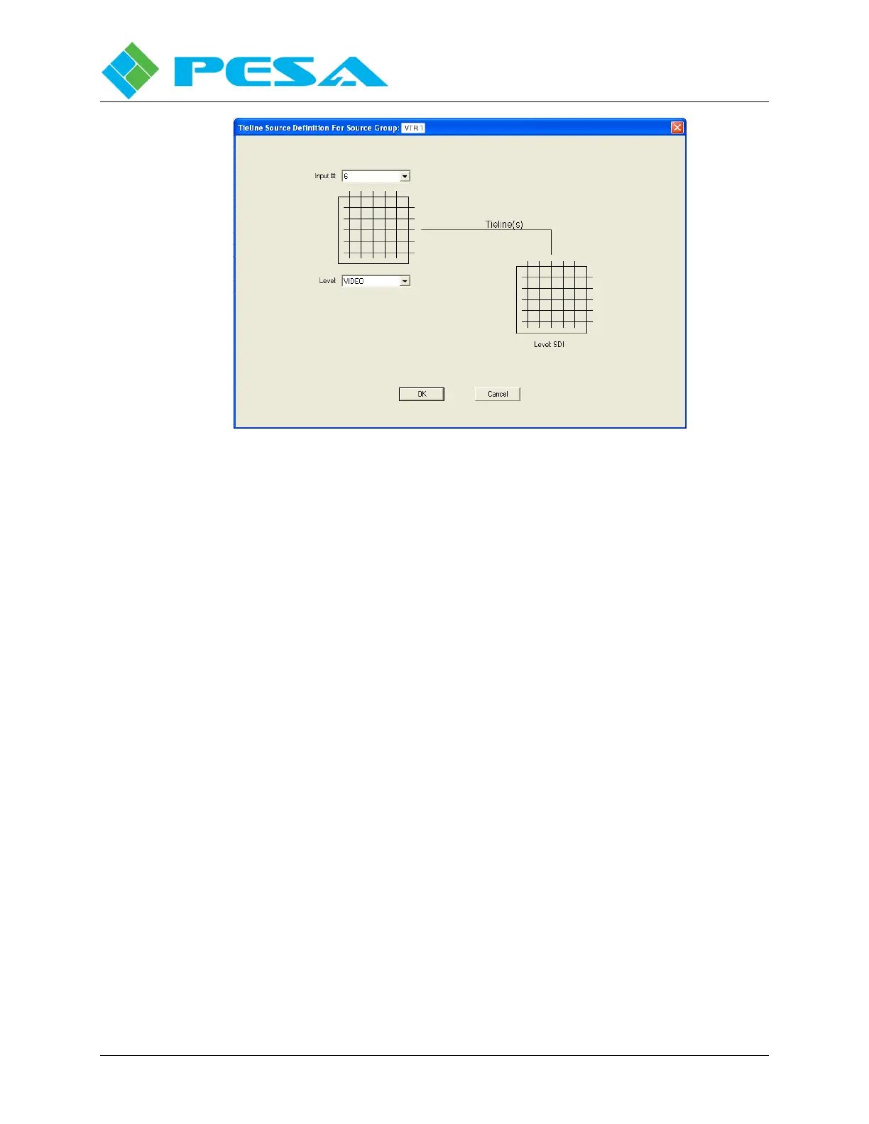
Figure 8-30 Tieline Configuration Screen
8.9.6 D
ESTINATIONS
Clicking the Destinations Command on the Configuration Command Tree accesses the
Destination Configuration Screen, Figure 8-31. This screen allows you to define all of the
destinations in the switcher configuration. From this screen each physical output from the
system is assigned a name, a panel designator and linked to a physical output of a router frame.
In router terminology, this screen essentially maps each physical destination (output) from the
router to its logical output in level and panel designator nomenclature.
Note the Destinations Screen is in the form of a database spreadsheet with data entries for each
destination made on individual rows from left to right. Each area of the Destinations set-up
screen is introduced in the following paragraphs:
8.9.6.1 Number
The left-most column is labeled NUMBER and is numerically sequential and automatically
filled in as sources are added. You can not change the entry in the Number column.
8.9.6.2 Name, Panel Name and Long Name
The next three columns allow you to assign identifying names and/or acronyms to each
destination according to the following formats:
Name – Any combination of up to 8 alphanumeric characters may be used to identify the
destination.
Panel Name - Any combination of up to 8 alphanumeric characters may be used to identify the
destination. The entry made in this column is the text string that will appear on system remote
control panels with display capability.