User Guide – PERC2000 System Controller
Publication 81-9059-0605-0, Rev. B
November 2010
Proprietary Information of
PESA 3-5
Using the RS-422 serial bus configuration allows for longer cable runs, up to 4000 feet in length.
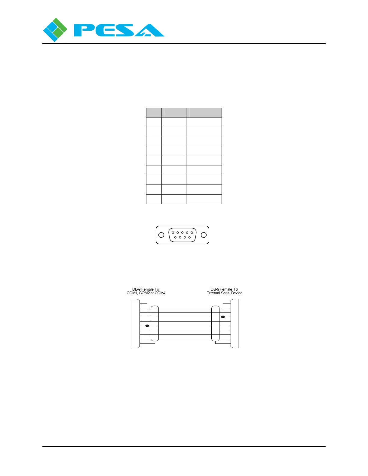
You may obtain serial bus cables from PESA or fabricate your own, using the connector pin
diagram shown by Figure 3-5 and pin-out diagram provided by Figure 3-8.
Table 3-2 RS-232 Serial Port Pin-Out Data
Pin Signal In/Out
1 CD Input
2 RX Input
3 TX Output
4 DTR Output
5 Ground
---
6 DSR Input
7 RTS Output
8 CTS Input
9 RI No Connect
Contact locations when viewed
from rear of chassis.
9876
Figure 3-5: (COM 1, COM 2 and COM 4) Connectors
CD (Carrier Detect)
RX (Receive Data)
TX (Transmit Data)
DTR (Data Terminal Ready)
SG (Signal Ground)
DSR (Data Set Ready)
RTS (Ready To Send)
CTS (Clear To Send)
RI (Ring Indicator)
DB-9 Female To:
3500Plus-S J13 or J14
CTS (Clear To Send)
RTS (Ready To Send)
DSR (Data Set Ready)
DTR (Data Terminal Ready)
RX (Receive Data) 2
RI (Ring Indicator)
SG (Signal Ground)
TX (Transmit Data)
9
8
7
6
5
4
3
CD (Carrier Detect) 1
3
9
7
8
5
6
2
4
DB-9 Female To:
PC
1
Figure 3-6: RS-232 CPU Link (Null Modem) Cable