User Guide – PERC2000 System Controller
Publication 81-9059-0605-0, Rev. B
November 2010
Proprietary Information of
PESA 6-5
6.4.1 C
IRCUIT
C
ARD
R
EMOVAL AND
I
NSTALLATION
Remove either system controller board as follows:
1. Pull the locking tabs on either side of the card tray assembly toward you to unseat the
card from its mating connectors.
2. Carefully slide the card tray assembly out of the chassis
Install a system controller board as follows:
1. Align the card tray assembly with the card guides in the chassis.
2. Carefully, insert the board into the chassis until the connectors on the board make contact
with the connectors on the backplane.
3. Firmly, push the board into the chassis until the board connectors are fully mated with the
backplane connectors.
6.4.2 P
OWER
S
UPPLY
M
ODULE
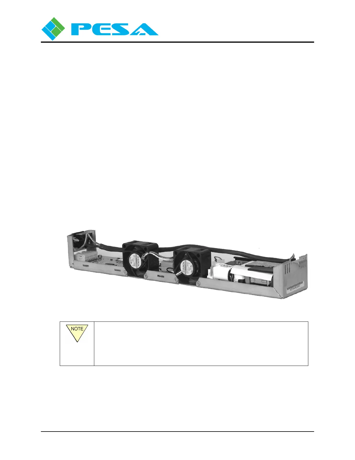
Power Supply modules slide into one of two available slots in the chassis frame. In redundant
power supply applications, a power supply module is used in both slots of a chassis frame. A
typical power supply module is shown in Figure 6-4. Power modules are hot-swappable.
Figure 6-4 Power Supply Module (Typical)
A fully configured PERC2000 stand-alone chassis contains two power
supply modules. Either power supply is capable of powering both system
controller boards, with the second power supply serving as a backup for the
first. One power supply may be removed and replaced while the other is
connected to the power source, and the system controller is operational.