Phoenix LT4 Lane Machine Operation, Maintenance, and Parts Manual
4-38 Rev. Date: 01/22 61-900040-000
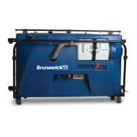
3. Disconnect the optical sensor cable.
4. Being careful not to cut into any wires, remove the wire tie securing the optical
sensor cable to the cable tie anchor.
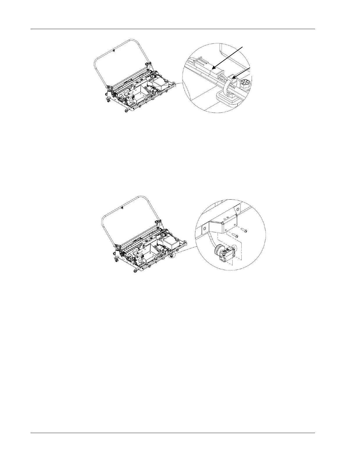
5. Remove the two screws that attach the optical sensor to its protective cover as
shown in Figure 4- 499.
6. Remove the grommet from the front panel of the machine and feed the connector
end of the sensor cable through it.
7. Feed the connector of the new optical sensor through the grommet and secure the
grommet in the hole of the front panel.
8. Secure the optical sensor to the protective cover using the two screws removed
earlier.
9. Connect the sensor cable to the control box cable.
10. Secure the optical sensor cable and wires from the vacuum head solenoid to the
cable tie anchor with a wire tie.
11. Reinstall the hood, vacuum hose, cleaner tank cap, and waste tank.
12. Refer to Section 4.3.7 – Adjusting the Optical Sensor.
Wire Tie &
Mounting Block