LUCAS® Chest Compression System – Service Manual
3323809-001, © 2017 Physio-Control, Inc.
68
9.10. How to replace the Battery Connector Board
9.10.1. Disassembling
Remove the Hood according to instructions in 9.1.
Warning: Always use ESD protection when handling PCB’s!
Place the hood upside down
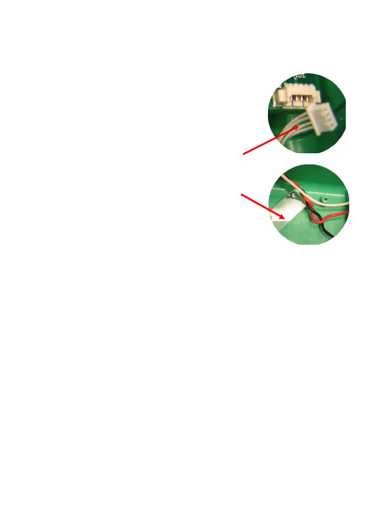
Disconnect the communication cable from the connector board
Remove one of the screws for the cable holder (Torx 6).
Loosen the second screw enough to rotate the cable holder as
shown in the picture.
Remove the four screws for the connector board (Torx20)
Remove the board
(make sure to remove all the old O-rings)
9.10.2. Reassembling
Place the supplied O-rings around all connector probes on the new board
Put the new board in place; make sure that the O-rings stay in place (Turn the hood
and place the board from below).
Note: If the plastic hole around the collapsed hood probe has been deformed it can be
drilled out by hand using a drill bit (Ø 4.6- 4.7 mm).
Place the four screws
Note: Turn the screws counter clockwise until the existing thread is found, then tighten to
13 in-lbs / 1.5 Nm.
Connect the communication cable and put back the cable holder.
Carefully re-install screws by turning the screws counter clockwise until the existing
thread are found, then tighten finger tight.
Re-install the Hood.
9.10.3. Test
Perform a Function Check according to Section 10.