EasyManua.ls Logo

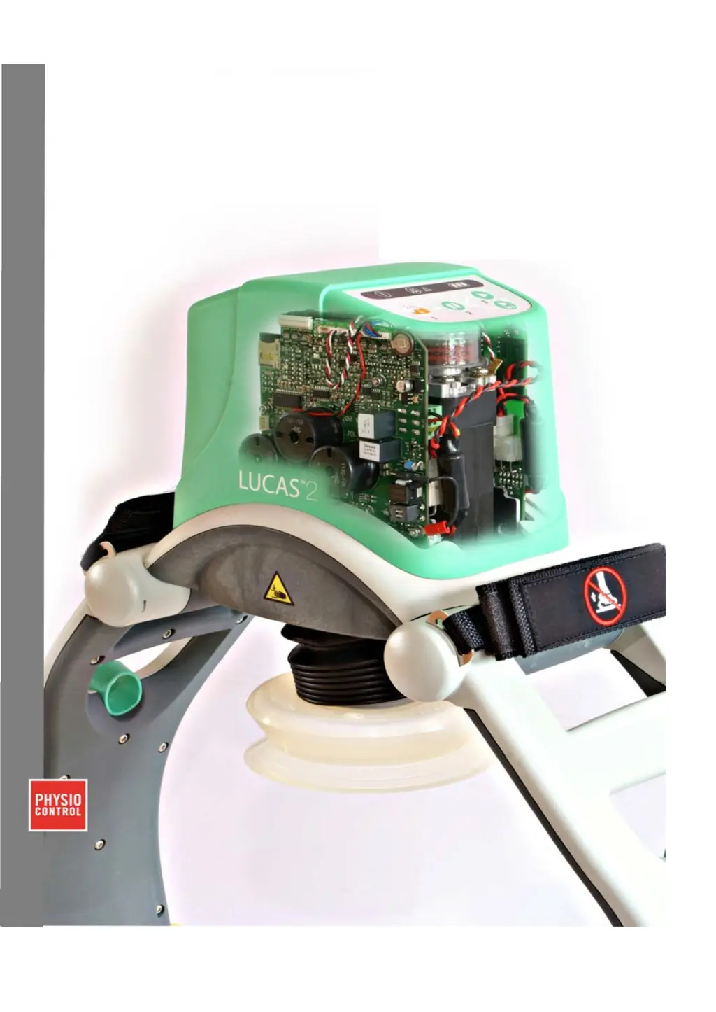
Physio Control lucas 2 - Service Manual

Physio Control lucas 2
77 pages
Print Icon
To Next Page IconTo Next Page
Loading...
1
LUCA2
Chest Compression System
Service
Manual
LUCAS® 2 Chest
Compression
System
-
Service Manual
3323809-001, © 2017
Physio-Control, Inc.

Table of Contents

Other manuals for Physio Control lucas 2

Questions and Answers

  • R
    Raymond SchultzSep 5, 2025
    What causes 'Control 2.5V Ref < 2V or > 3V' on Physio Control Medical Equipment?
    • J
      Jeffrey LaraSep 5, 2025
      If your Physio Control Medical Equipment displays 'Control 2.5V Ref < 2V or > 3V', it indicates an electrical fault, a Control board pin connected to the back plate, or a POT +2.5V shortcut. Check the POT or replace the Control board.
  • L
    lawrencesimsAug 25, 2025
    What to do if my Physio Control Medical Equipment shows 'Real Time Clock Fault'?
    • F
      fharperAug 25, 2025
      If your Physio Control Medical Equipment displays a 'Real Time Clock Fault', it could be due to a read fault at start, an I2C fault, or a low “BAT1” voltage. To resolve this, charge “BAT1” by starting the device and pressing PAUSE, leaving it ON for 30 minutes. Then, set the correct time and date using the LUCAS2.exe program. Restart the equipment and check for the COM_RTC warning. If the issue persists, consider replacing the Control board.
  • D
    Deborah BlackAug 25, 2025
    How to troubleshoot 'High Current detected at Start' in Physio Control Medical Equipment?
    • L
      Lindsey LopezAug 26, 2025
      If your Physio Control Medical Equipment detects high current at start, it might be due to a fault reading current to the motor, broken driver FETs, or a +/- 12V supply fault. If needed, replace the Control board.
  • S
    Scott DiazSep 13, 2025
    What does 'Current fault' mean for Physio Control Medical Equipment?
    • B
      Beth VargasSep 13, 2025
      If your Physio Control Medical Equipment displays 'Current fault', it means the mean current to the motor is >20A, there is a jam of compression module, or a current read fault. Check the motor and compression module. Consider replacing the Control board.
  • S
    sarah08Sep 23, 2025
    What does 'I2C communication fault with Control CPU' mean for Physio Control Medical Equipment?
    • A
      aprildavisSep 23, 2025
      If your Physio Control Medical Equipment displays 'I2C communication fault with Control CPU', it indicates an I2C communication fault at mode change or another fault detected by Control. Check if another fault is detected by Control and check the cable between boards.
  • K
    Kenneth YoungSep 9, 2025
    What does 'Halt or reverse by Protective System' mean for Physio Control Medical Equipment?
    • J
      Jennifer NavarroSep 9, 2025
      If your Physio Control Medical Equipment halts or reverses by the Protective System, it means the active mode was disabled by the Protective system. Check Protective error’s.
  • D
    dannyrobinsonSep 1, 2025
    What does 'No end of Protective Current Test (time out)' mean for Physio Control Medical Equipment?
    • A
      Autumn GordonSep 1, 2025
      If your Physio Control Medical Equipment displays 'No end of Protective Current Test (time out)', it indicates a Protective current read fault or I2C communication faults. Check for Protective errors and consider replacing the Protective board.
  • J
    Jeremy GutierrezSep 23, 2025
    What does 'Piston Ratio fault' mean on Physio Control Medical Equipment?
    • L
      Louis GloverSep 23, 2025
      If your Physio Control Medical Equipment displays 'Piston Ratio fault', it is caused by too high load. Check the load.
  • D
    Douglas BarreraSep 18, 2025
    What does 'Buzzer fault' mean for Physio Control Medical Equipment?
    • A
      Annette SanfordSep 18, 2025
      If your Physio Control Medical Equipment displays 'Buzzer fault', it means there is a buzzer fault. Replace the Protective board.
  • L
    Lori NewmanAug 28, 2025
    How to resolve 'No Communication between Protective and/or Battery- Charger CPU's at start' on Physio Control Medical Equipment?
    • S
      Sonya PerryAug 28, 2025
      If your Physio Control Medical Equipment shows 'No Communication between Protective and/or Battery- Charger CPU's at start', it is caused by I2C communication faults or a halted Protective or Charger CPU. Replace the cable between the boards or replace the Protective board.

Summary

Important User Information

Scope of Service Manual

Defines the coverage and applicability of the service manual.

Required Skills for Technicians

Lists the necessary qualifications and training for service technicians.

Disclaimer of Liability

States limitations of liability for product misuse or consequential damages.

Patient Safety Fault Reporting

Procedure for reporting any failures affecting patient or user safety.

Trademarks

Identifies the trademark holder for LUCAS®2.

Related Information and Documents

References other relevant documents for additional information.

Service Administration and Procedures

Service Reporting and Device Tracking

Details on reporting service actions and tracking device modules.

Recycling Information

Guidelines for proper recycling of device materials.

Responsibility for Information

Identifies who is responsible for the accuracy of manual content.

Introduction to LUCAS 2

Intended Use of LUCAS 2

Specifies the device's purpose and limitations for performing chest compressions.

Warnings and Precautions

Electrical Hazard Safety

Precautions to take when working with electrical components.

Chemical Hazard Safety

Safety measures related to battery chemicals and leakage.

ESD Protection Measures

Guidelines for protecting against electrostatic discharge when handling electronics.

Function of the LUCAS Device

Electronics System Overview

Details on battery, PCBs, user panel, and cooling fan.

Compression Mechanism Function

Explains how the device generates chest compressions.

Components of the LUCAS 2 System

Lists and illustrates all physical parts of the LUCAS® 2 system.

LUCAS 2 Program Loader

Software Installation

Steps for installing the program loader software and drivers.

Connecting the Device to Software

Procedure to establish a connection between the LUCAS device and the computer.

Using the Program Loader Software

Instructions for operating the software interface and understanding its display.

Updating the Device Program

Procedures for updating the software on the LUCAS device.

Troubleshooting Failed Calibration

Addresses issues and solutions for calibration errors encountered during software use.

Understanding Checksums

Information on how to verify installed program versions using checksums.

Changing Device ID

Procedure to modify the device's unique identification number.

Setting Device Time and Date

Instructions for synchronizing the device's internal clock.

Storing and Printing Software Views

Functionality for saving and printing status views from the software.

Troubleshooting

Normal Operation Indications and Alerts

Interpreting visual and audible signals during normal device operation.

LUCAS Malfunction Alarms

Details on device malfunction alarms, their causes, and results.

System Error Codes

Lists and explains error codes from the Control, Protective, and Charger CPUs.

Control CPU Error Codes

Specific error codes originating from the Control CPU and their probable causes.

Protective CPU Error Codes

Specific error codes originating from the Protective CPU and their probable causes.

Charger CPU Error Codes

Specific error codes originating from the Charger CPU and their probable causes.

Practical Troubleshooting Steps

General advice and common checks for diagnosing device issues.

Spare Parts and Accessories

Service Spare Parts List

Detailed list of spare parts available for servicing the LUCAS device.

Other Orderable Spare Parts

List of additional spare parts that can be ordered for the device.

Accessory List

List of accessories compatible with the LUCAS device.

Tools Required for Service

Standard Tools List

List of common tools needed for performing maintenance and repairs.

Special Tools

List of specific tools recommended for LUCAS service.

Substances Used in Maintenance

Lists lubricants, fluids, and other substances required for maintenance.

Software for Maintenance

Lists the software programs required for device maintenance and diagnostics.

Preventive Maintenance

Yearly Maintenance Procedure

Step-by-step guide for performing annual maintenance on the LUCAS device.

Cleaning Fan and Mesh Grill

Instructions for cleaning the electric fan and mesh grill.

Compression Module Lubrication

Procedure for lubricating the compression module's carry ball screw.

Claw Lock Lubrication

Instructions for lubricating the claw lock mechanism.

Replacing Parts and Modules

Replacing the Hood and Hood Bracket

Procedure for removing and installing the hood and its bracket.

Replacing the Bellows

Instructions for replacing the bellows component of the device.

Replacing the Compression Module

Procedure for replacing the main compression unit.

Replacing the Drive Belt

Instructions for replacing the drive belt.

Replacing the Electric Motor

Procedure for replacing the electric motor.

Replacing the Controller PCB

Procedure for replacing the main control board.

Replacing the Protective PCB

Procedure for replacing the protective control board.

Replacing the Electric Fan

Procedure for replacing the electric fan.

Replacing the Support Leg

Procedure for replacing a support leg.

Replacing the Battery Connector Board

Procedure for replacing the battery connector board.

Replacing the Power Inlet

Procedure for replacing the power inlet.

Replacing the Main Body;Frame Assembly

Procedure for replacing the main body or frame assembly.

Function Check Procedures

Introduction to Function Check

Overview of the process to verify device functions after repair or maintenance.

Mechanics Test Procedures

Tests to verify the proper mechanical operation of the device.

Piston and Claw Lock Mechanism Checks

Detailed checks for the piston and claw lock mechanisms.

Electronics Test Procedures

Tests to verify the proper electronic functions and indicators of the device.

Physio Control lucas 2 Specifications

General IconGeneral
BrandPhysio Control
Modellucas 2
CategoryMedical Equipment
LanguageEnglish

Related product manuals