User Manual
E727T0005, valid for E-727
BRO, 2019-06-28
Physik Instrumente (PI) GmbH & Co. KG, Auf der Roemerstrasse 1, 76228 Karlsruhe, Germany Page 146 / 240
Phone +49 721 4846-0, Fax +49 721 4846-1019, Email info@pi.ws, www.pi.ws
Data Packet Definition
Data Frame
The following data packet definition is valid for both directions.
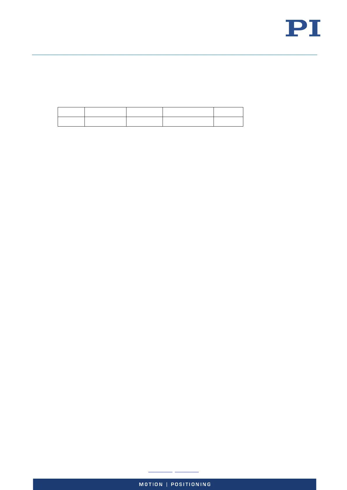
PID/ST CTR2/CNT1 DS2/Flags DS1 CRC-16
1 Byte 1 Byte 2 Bytes CNT1 x 4 Bytes 2 Bytes
The data frame consists of the following fields:
PID/ST Status bits, explaned later
CTR2/CNT1 CTR2 = control bits for data segment 2,
CNT1 = data word counter for data segment 1 (1 word = 4 bytes)
DS2/Flags Data segment 2, for slow data transfer or for flag bits
DS1 Data segment 1, for fast position value transfer
CRC-16 Cyclic redundancy check of PID/ST, CTR2/CNT1, DS2/Flags and DS1
The data frame is for transportation of user data and consist of two data segments DS1 and DS2.
Data segment 1 (DS1) is used to transfer data which can be updated each servo-loop cycle. For the
direction from host to PI-controller DS1 is used to transfer axis target position data (closed-loop
operation) or open-loop control values (open-loop operation). For the direction from PI-controller
to host DS1 is used to transfer the current axis position.
Whenever the PI-controller receives new target position data transferred by data segment 1, the
PI-controller latches this new data and overwrites the old data. In case that a CRC error occurs and
no new target position data could be received, the PI-controller uses the latched target position
data which was most recently received.
Data segment 2 (DS2) is used for slow data transfer, for example for GCS-commands. DS2 transfers
fragments of data from transmit fifo to the receiver fifo where data is collected again. Therefore
the transfer of a GCS command normally will take several servo-loop cycles.
When data segment 2 transfers no slow data then flag bits are transferred. This is a cyclic transfer
like with data segment 1.
CRC-16 Generation
The CRC-16 of PID/ST, CTR2/CNT1, DS2/Flags and DS1 is appended after packet data.
The following polynomial is used to generate the code (Start value 0xFFFF): 1 + x
2
+ x
15
+ x
16
The CRC-16 word is transferred with the highest bit first and the lowest bit last.