User Manual
E727T0005, valid for E-727
BRO, 2019-06-28
Physik Instrumente (PI) GmbH & Co. KG, Auf der Roemerstrasse 1, 76228 Karlsruhe, Germany Page 227 / 240
Phone +49 721 4846-0, Fax +49 721 4846-1019, Email info@pi.ws, www.pi.ws
Digital I/O
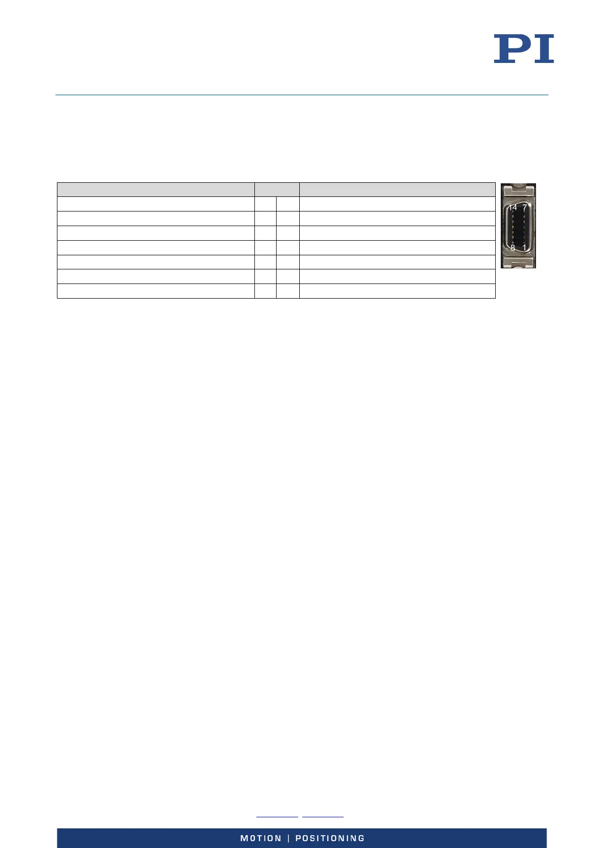
„Digital I/O“ - MDR14
Function Pin Function
3.3 V out, internal resistance: 100 ohm 14 7 not connected
Digital In 1 13 6 not connected
Digital In 2 12 5 Digital Out 1
Digital In 3 11 4 Digital Out 2
not connected 10 3 Digital Out 3
not connected 9 2 Digital In 4 / Reset (active low)
Output of the servo cycles 8 1 GND
Digital inputs (pins 2, 11, 12, 13):
TTL (low: 0 to 0.8 V, high: 2 to 5 V, max.: 5 V)
When nothing is connected to a digital input, the signal level is high due to an
internal pull-up with 10 kohm resistor.
Digital In 4 (pin 2) can be configured as reset input using the Reboot On DIO Input
parameter (ID 0x0e001500). Changes of the parameter value become effective
immediately. The value of the parameter enables/disables the Reset input as
follows:
− 0 = OFF: Reset input is disabled (default setting)
− 1 = ON: Reset input is enabled. If the signal level on the Reset input becomes
low, the E-727 is rebooted (same behaviour as with the RBT command).
Digital outputs (pins 3, 4, 5, 8):
High level:
− at -2 mA output current => min. 2.2 V
− at -0.1 mA output current => min. 3.0 V
Low level:
− at +2 mA output current => max. 0.6 V
− at +0.1 mA output current => max. 0.21 V
The servo cycle output on pin 8 is not accessible for commands.