User Manual
E727T0005, valid for E-727
BRO, 2019-06-28
Physik Instrumente (PI) GmbH & Co. KG, Auf der Roemerstrasse 1, 76228 Karlsruhe, Germany Page 158 / 240
Phone +49 721 4846-0, Fax +49 721 4846-1019, Email info@pi.ws, www.pi.ws
Data Transmission via SPI
Data Line Definition
SCLK Serial data clock from host Output Input
CS Data word latch Output Input
MISO Master Input Slave Output Date line.
Data output changes with positive edge of SCLK
Input Output
MOSI Master Output Slave Input Date line.
Data input is latched with falling edge of SCLK
Output Input
LDAT Latch / Load data:
Falling edge latches sender data
Rising edge loads receiver data
Output Input
Serial data clock from PI-controller
Packet Transmission
Because the SPI interface has only one clock the data packet transmission of host and PI-controller
runs simultaneously. The PI-controller responds at least one cycle after the host command was
received. This applies to the GCS commands and their responds which are transferred by data
segment 2 and which need to be acknowledged by the receiver.
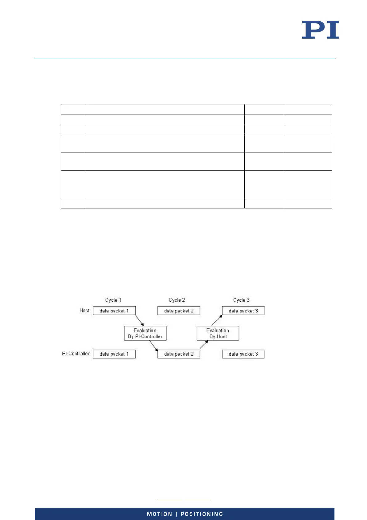
In the following example, data packet 2 sent by the PI-controller contains the response to the
command contained in data packet 1, sent by the host: For example, the host sends the first data
fraction with data packet 1, the PI-controller sends an acknowledge to this with data packet 2 and
then the host can send the next fraction with data packet 3.
The data packets have the same format as described in the data packet definition section (p. 145).