User Manual
E727T0005, valid for E-727
BRO, 2019-06-28
Physik Instrumente (PI) GmbH & Co. KG, Auf der Roemerstrasse 1, 76228 Karlsruhe, Germany Page 159 / 240
Phone +49 721 4846-0, Fax +49 721 4846-1019, Email info@pi.ws, www.pi.ws
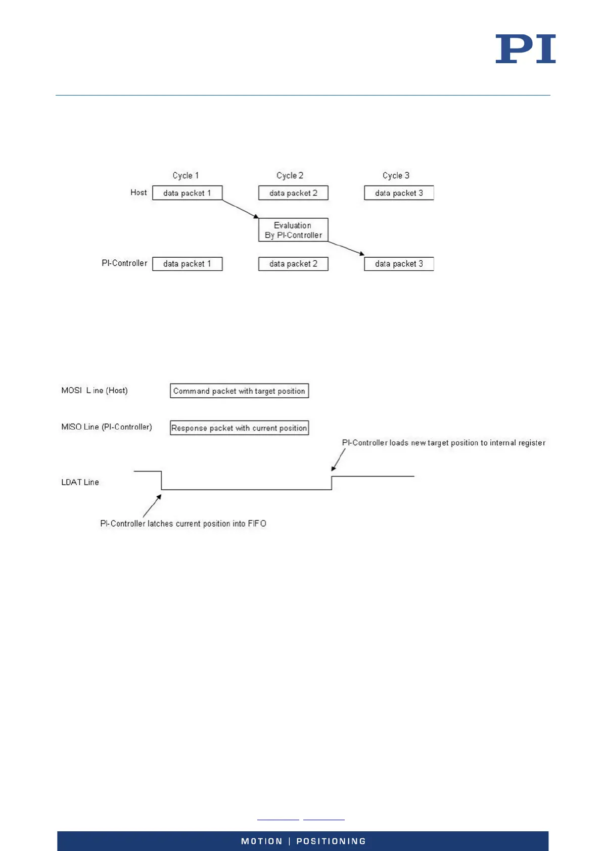
It is also possible that the PI-controller needs more than one cycle for processing of data which was
sent by the host. In the following example the PI-controller needs one extra cycle for command
data processing so that data packet 3 from PI-controller is the answer to data packet 1 from the
host side.
LDAT: Latch Data Output / Load Data Input
With the LDAT command the input and output data of the PI-controller is synchronized with the
command interface. The falling edge of the LDAT line latches the current position values of all axis
into the output FIFO. With the next response packet the position values will be sent to the host.
With the rising edge of the LDAT line the most recently received data is loaded into the target
position register of the PI-controller.
CS: Data Word Latch
The CS-signal divides the command packet into 16-bit data words. While the LDAT is active low
throughout a command packet transmission the CS-signal becomes low while a 16-bit data word is
transferred. With the rising edge of CS the controller internally saves the last 16-bit data word.
SCLK: Serial Data Clock from Host
The serial clock is active only while data bits are transferred. The reason for this is that some
devices do not have enable inputs for the serial clock.