User Manual
E727T0005, valid for E-727
BRO, 2019-06-28
Physik Instrumente (PI) GmbH & Co. KG, Auf der Roemerstrasse 1, 76228 Karlsruhe, Germany Page 156 / 240
Phone +49 721 4846-0, Fax +49 721 4846-1019, Email info@pi.ws, www.pi.ws
OnTarget-Flag Transfer
As long as data segment 2 is not used for GCS command transfer (DataCtrl = 0,0) the two bytes are
used to transfer flag bits. When the sender is the PI-controller then the OnTarget flags (ONT),
ServoOn flags (SON), and Overflow flags (OVF) for axis 1 to axis 4 (A1 to A4) are sent:
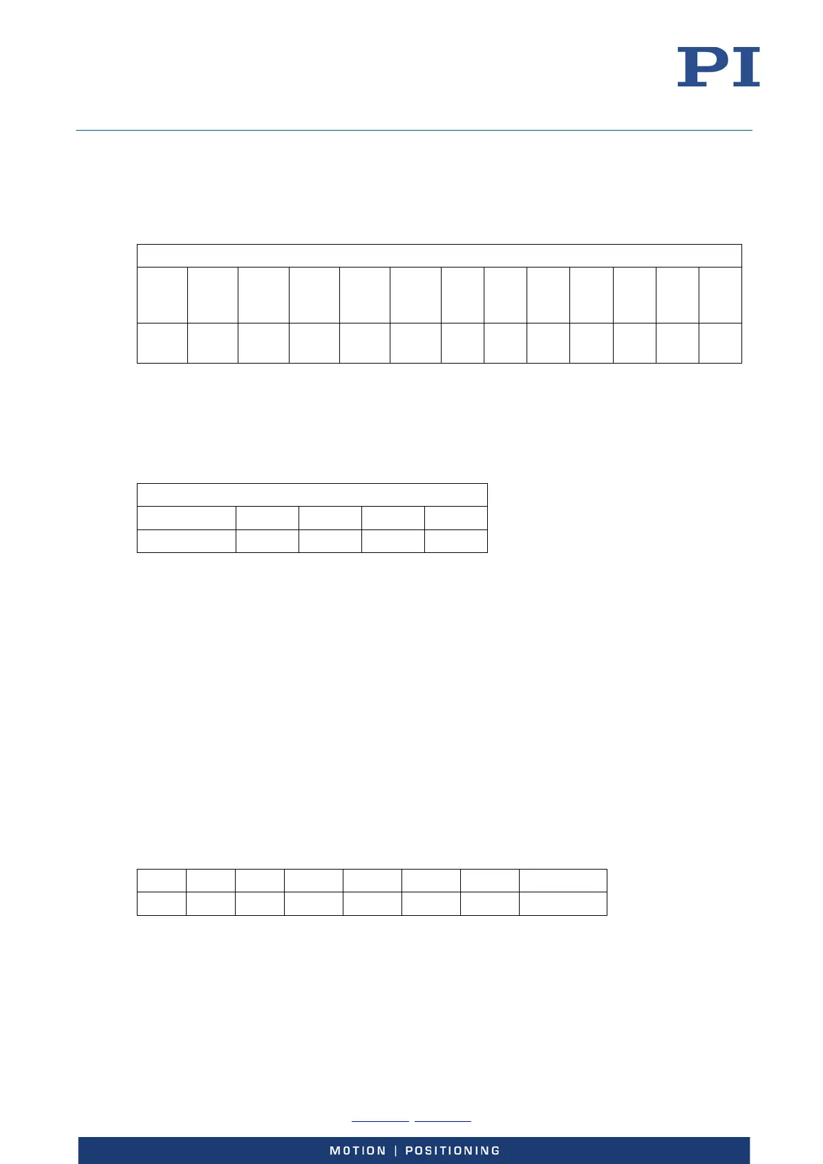
Data segment 2
Bit 15 Bit 14 Bit 13 Bit 12 Bit 11 Bit 10 Bit 9 Bit 8 Bit 7
to
Bit 4
Bit 3 Bit 2 Bit 1 Bit 0
A4
A3
A2
A1
A4
A3
A2
A1
A4
A3
A2
A1
Transfer of Servo-Mode Changing Commands
As long as data segment 2 is not used for GCS command transfer (DataCtrl = 0,0) the two bytes are
used to transfer flag bits. When the sender is the host then command bits to change the servo
mode (SMC) are transferred for axis 1 to axis 4 (A1 to A4).
Bit 15 to Bit 4 Bit 3 Bit 2 Bit 1 Bit 0
Changing the SMC bit changes the servo mode of the addressed axis as follows:
A change from 0 to 1 switches the servo mode of the addressed axis on (closed-loop
operation).
A change from 1 to 0 switches the servo mode of the addressed axis off (open-loop
operation).
Only changes of the SMC bits have an effect on the servo mode. Therefore the first servo-mode
changing command which is received by the E-727 after power-on is saved internally by the E-727
and is only used to detect changes of the SMC bits.
GCS Command Transfer
GCS commands are transferred in ASCII format.
The following example shows the transfer of a command to switch on the servo mode for of axis 2.
The GCS representation is:
SVO 2 1
The representation as ASCII numbers, including spaces and terminating line feed, is:
S V O Space 2 Space 1 Line feed
0x53 0x56 0x4F 0x20 0x32 0x20 0x31 0x0A
For this command eight characters must be transferred and so four transfer packets are needed. In
this example only one axis is transferred in data segment 1 (CNT1 = 1). Before the transmission of
the actual data can be started the initialization packet must be sent to initialize the receiver’s
toggle bit. As initial value for SToggle “1” is assumed.