User Manual
E727T0005, valid for E-727
BRO, 2019-06-28
Physik Instrumente (PI) GmbH & Co. KG, Auf der Roemerstrasse 1, 76228 Karlsruhe, Germany Page 230 / 240
Phone +49 721 4846-0, Fax +49 721 4846-1019, Email info@pi.ws, www.pi.ws
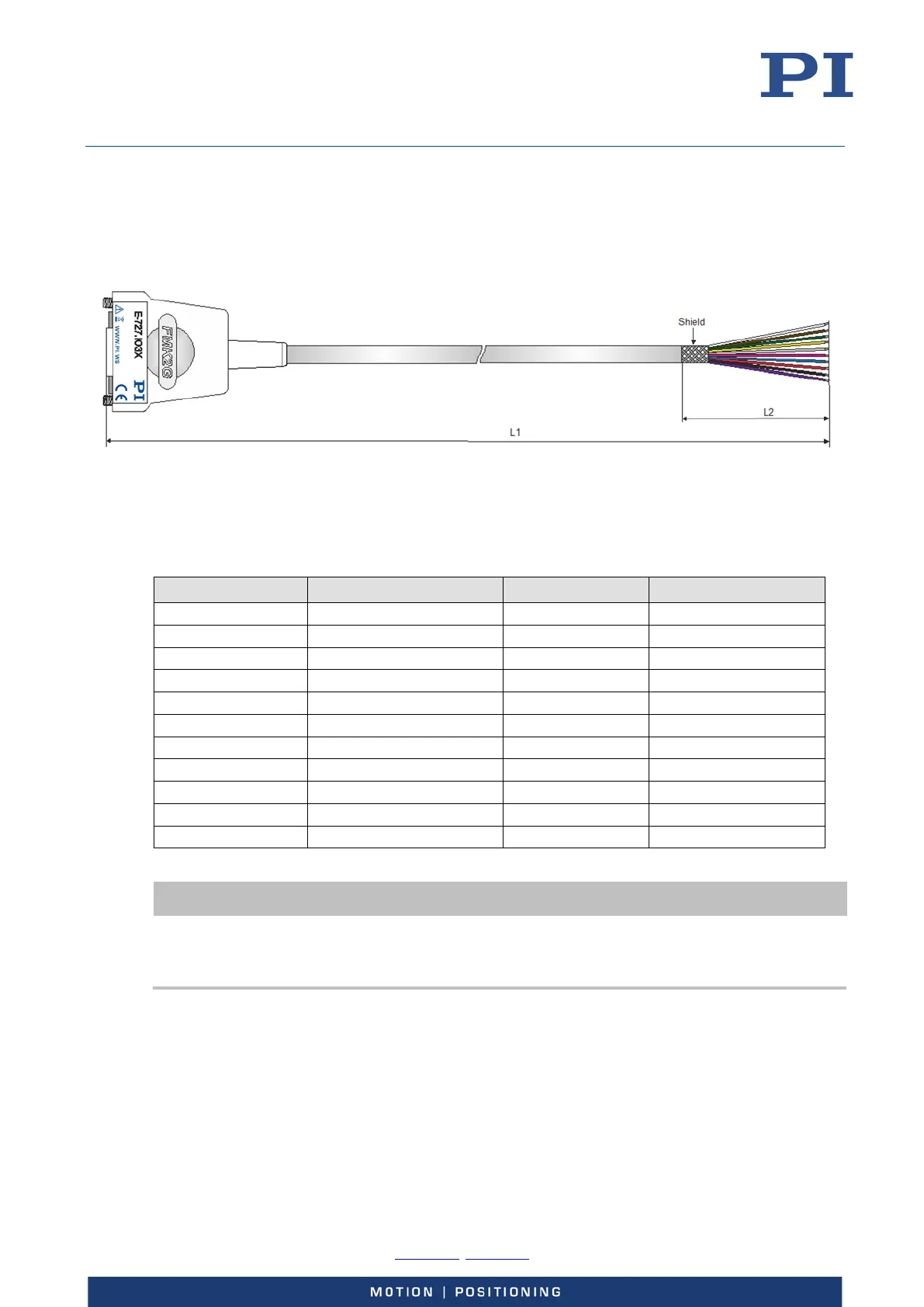
E-727.IO3x Analog Input Cable
The E-727.IO3x analog input cable splits the input lines of the Analog I/O socket (p. 228) up into
separate wires.
Figure 44: E-727.IO3x cable, D-Sub 15 (m) to open end
L1 = 1 m ±10 cm
L2 = 6 cm ±1 cm
D-Sub 15 (m) Signal
Wire pair Color
1 GND Pair 1 brown
9 -Analog In 1 Pair 2 green
2 +Analog In 1 Pair 2 yellow
10 -Analog In 2 Pair 3 grey
3 +Analog In 2 Pair 3 pink
11 -Analog In 3 Pair 4 blue
4 +Analog In 3 Pair 4 red
12 -Analog In 4 Pair 5 black
5 +Analog In 4 Pair 5 purple
13 GND Pair 1 white
Hood Shield Cable shield ---
INFORMATION
When using an analog input of the E-727, both the corresponding +Analog In and –Analog In line
must be wired.
Observe the wiring information in “E-727.xxxA, E-727.xxxAx: Analog I/O“ (p. 228).