User Manual
E727T0005, valid for E-727
BRO, 2019-06-28
Physik Instrumente (PI) GmbH & Co. KG, Auf der Roemerstrasse 1, 76228 Karlsruhe, Germany Page 226 / 240
Phone +49 721 4846-0, Fax +49 721 4846-1019, Email info@pi.ws, www.pi.ws
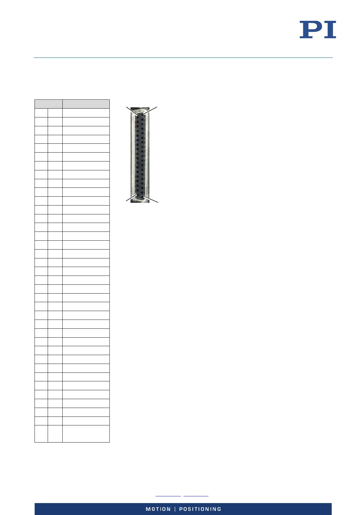
E-727 for Piezoresistive Sensors and SGS: Socket for Piezo Stages
„-30 to +130 V“ – D-Sub 37 (f)
Pin Function
Either the lines for the PT1000 temperature sensor or
the lines for the 4
th
piezoresistive or strain gauge sensor
can be used since they share input signal channel 4 of
the E-727. The use of input signal channel 4 can be
configured via the value of the Sensor Range Factor
parameter (ID 0x02000100) as follows:
1: Use with an piezoresistive or strain gauge sensor
(pins 6, 24, 25)
2: Use with a PT1000 temperature sensor (pins 1, 20)
With E-727.3RDA, .3RDAx, .3SDA and E-727.3SDAx
models, the following values of the Sensor Range Factor
parameter are supported for input signal channel 4 in
addition, deactivating both the PT1000 and 4
th
piezoresistive or strain gauge sensor:
3: Use as analog input 1 with a range of ±5 V (input
via pins 2 and 9 on the Analog I/O socket (p. 228))
4: Use as analog input 1 with a range of ±10 V (input
via pins 2 and 9 on the Analog I/O socket)
With E-727.3RDA, .3RDAx, .3SDA and .3SDAx models:
The Piezo Ch 4 lines of the socket for piezo stages share
output signal channel 4 of the E-727 with analog output
1 (pin 8 on the Analog I/O socket). The use of output
signal channel 4 can be configured via the value of the
Select Output Type parameter (ID 0x0A000003) as
follows:
1: Output voltage for a piezo actuator in the stage,
output as Piezo Ch 4 (pins 19 and 37)
2: Position monitor of an axis. The value of the Select
Output Index parameter (ID 0x0A000004)
determines the axis whose position is to be output.
Output on pin 8 of the Analog I/O socket (p. 228).
5: Control signal for an external amplifier. The value
of the Select Output Index parameter (ID
0x0A000004) determines the output signal channel
whose control value is to be output. Output on pin 8
of the Analog I/O socket.
If a total of four piezo actuators are present in the
stage(s), output signal channel 4 must always be
configured for use as output voltage (Piezo Ch 4). Note
that PI will supply E-727 and the piezo stage(s) as a
system with appropriate settings. If you are not sure
whether your system can be configured for output of
position monitor or control signal, contact our customer
service department (p. 234).
1 PT1000+
20 PT1000-
2 GND
21 ID-Chip Ch 1
3 ID-Chip Ch 2
22 ID-Chip-GND
4 ID-Chip Ch 3
23 ID-Chip Ch 4
5 ID-Chip-GND
24 SGS Ch 4 +
6 SGS Ch 4 -
25 SGS Ch 4 Ref
7 GND
26 SGS Ch 3 +
8 SGS Ch 3 -
27 SGS Ch 3 Ref
9 GND
28 SGS Ch 2 +
10 SGS Ch 2 -
29 SGS Ch 2 Ref
11 GND
30 SGS Ch 1 +
12 SGS Ch 1 -
31 SGS Ch 1 Ref
13 GND
32 Reserved
14 Reserved
33 Reserved
15 Reserved
34 Piezo Ch 1 -
16 Piezo Ch 1 +
35 Piezo Ch 2 -
17 Piezo Ch 2 +
36 Piezo Ch 3 -
18 Piezo Ch 3 +
37 Piezo Ch 4 -
19 Piezo Ch 4 +