User Manual
E727T0005, valid for E-727
BRO, 2019-06-28
Physik Instrumente (PI) GmbH & Co. KG, Auf der Roemerstrasse 1, 76228 Karlsruhe, Germany Page 81 / 240
Phone +49 721 4846-0, Fax +49 721 4846-1019, Email info@pi.ws, www.pi.ws
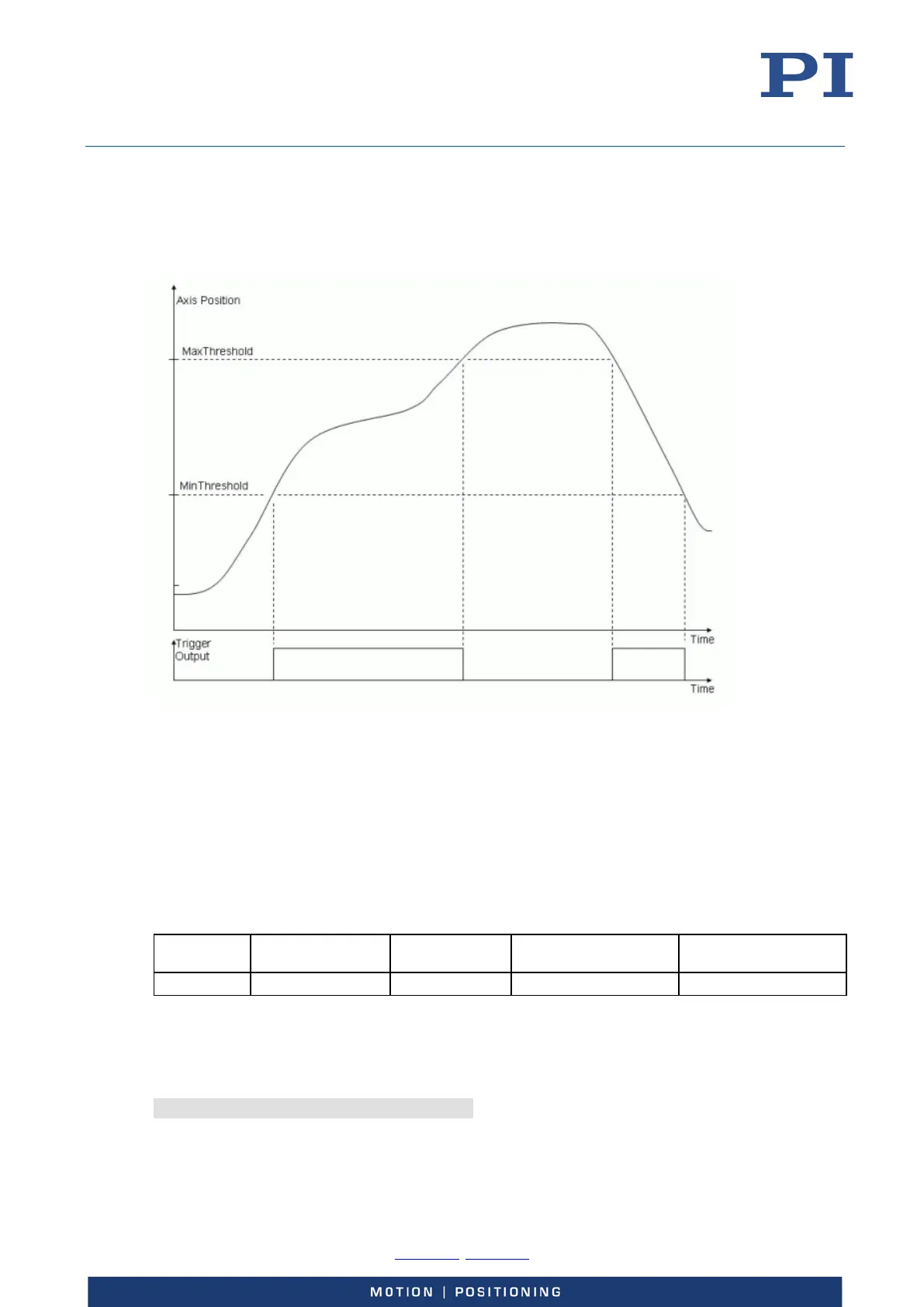
Example—"MinMax Threshold" Trigger Mode
With the "MinMax Threshold" trigger mode, a band is specified with MinThreshold and
MaxThreshold (<CTOPam> IDs 5 and 6). When the axis position is inside the specified band then
the trigger output line is set high, otherwise it is set low.
Figure 27: "MinMax Threshold" Trigger Mode
The following parameters must be set for the digital output line which is to be used for trigger
output (<TrigOutID>):
Axis (<CTOPam> = 2)
TriggerMode (<CTOPam> = 3)
MinThreshold (<CTOPam> = 5)
MaxThreshold (<CTOPam> = 6)
General notation of the CTO command for this mode (in fact, the command arguments can be
divided in four "portions", each starting with the <TrigOutID> declaration):
Command
mnemonic
Axis selection
Trigger mode
selection
Min threshold setting Max threshold setting
CTO
<TrigOutID> 2 Axis
<TrigOutID> 3 3
<TrigOutID> 5 min.pos. <TrigOutID> 6 max.pos.
Instead of using the CTO command, you can also set the values of the corresponding parameters
with SPA or SEP, see “Configuring Trigger Output” (p. 69) for a parameter list.
Example: The digital output line 1 is to be set high whenever the axis position of axis 1 is higher
than 0.3 µm and lower than 0.6 µm. Send:
CTO 1 2 1 1 3 3 1 5 0.3 1 6 0.6