User Manual
E727T0005, valid for E-727
BRO, 2019-06-28
Physik Instrumente (PI) GmbH & Co. KG, Auf der Roemerstrasse 1, 76228 Karlsruhe, Germany Page 228 / 240
Phone +49 721 4846-0, Fax +49 721 4846-1019, Email info@pi.ws, www.pi.ws
E-727.xxxA, E-727.xxxAx: Analog I/O
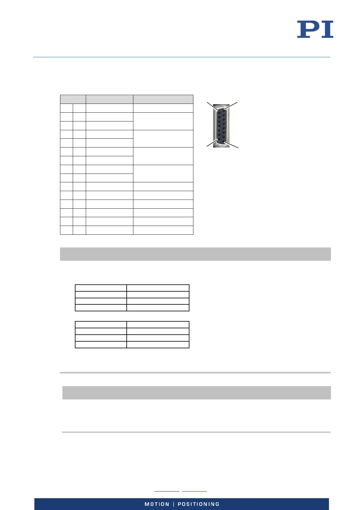
„Analog I/O“ – D-Sub 15 (f)
Pin Function Channel identifier*
1 GND -
9 -Analog In 1 Input signal channel 4
2 +Analog In 1
10 -Analog In 2 Input signal channel 5
3 +Analog In 2
11 -Analog In 3 Input signal channel 6
4 +Analog In 3
12 -Analog In 4 Input signal channel 7
5 +Analog In 4
13 GND -
6 GND -
14 Sensor Monitor 1 -
7 Sensor Monitor 2 -
15 Sensor Monitor 3 -
8 Analog Out 1 Output signal channel 4
* For further information on channel identifiers, see „Axes, Channels, Functional Elements” (p. 22).
INFORMATION
When using an analog input of the E-727, both the corresponding +Analog In and –Analog In line must be
wired.
Connect a differential signal (+analog, -analog, GND) as follows:
Connect a single-ended signal as follows (recommended):
* If it is not possible to connect –Analog In to GND on the customer side, -Analog In should be
connected to GND on the E-727 side.
In either case, use a shielded cable.
INFORMATION
To achieve the highest possible resolution and eliminate potential interference that affects the cable used:
Filter the analog output signal of the E-727 in a suitable way, e.g., before you convert it to a digital
format. Recommended: low-pass filter with max. 100 kHz cut-off frequency (characteristics: single
pole, 6 dB/octave)