User Manual
E727T0005, valid for E-727
BRO, 2019-06-28
Physik Instrumente (PI) GmbH & Co. KG, Auf der Roemerstrasse 1, 76228 Karlsruhe, Germany Page 68 / 240
Phone +49 721 4846-0, Fax +49 721 4846-1019, Email info@pi.ws, www.pi.ws
Start/Stop Mode
WGR Start Recording
Synchronous to Wave
Generator
Triggers recording
For detailed command descriptions see the GCS commands manual PZ281E. For the identifiers of
the items which can be addressed with the commands see "Axes, Channels, Functional Elements"
(p. 22).
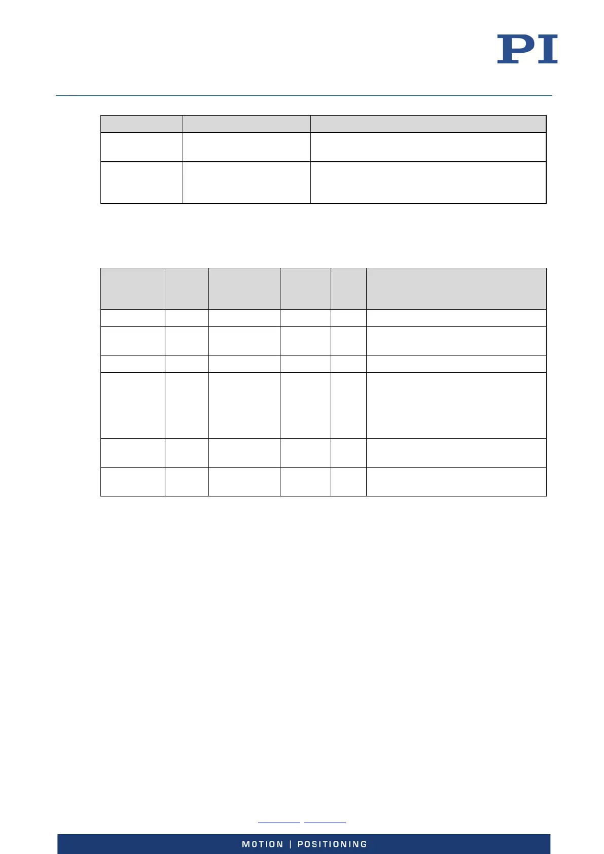
Parameter
ID
CCL for
Write
Access
Item Type
Concerned
Max. No.
of
Items
Data
Type
Parameter
Description
0x16000000 1 System 1 INT Data Recorder Table Rate
Max Number of Data Recorder
Channels
0x16000200 3 System 1 INT Data Recorder Max Points
0x16000300 1 System 1 INT Data Recorder Chan Number; the
available data recorder points are
allocated in equal shares to the
number of tables given by this
parameter
table
0x16000701 1 Data recorder
table
8 INT DRC Record Option
See "Parameters" (p. 185) for more information regarding the controller parameters and their
handling.
Using Digital Input
The digital input lines of theE-727 are available on the Digital I/O socket, see p. 227 for the lines
and pinout.
The values of all digital input lines can be recorded, see the DRC command for details.
The IN1 to IN4 input lines can be used to start data recording, see the DRT command for details.
The IN 4 line can also be configured as reset input, see p. 227 for details. In this case, do not use
IN4 to start data recording.
The IN1 and IN2 input lines can be used in conjunction with the WGO command to trigger the
wave generator output (IN1 and IN2) and to stop it (IN2). See "Wave Generator Started by Trigger
Input" (p. 111) for an example.