User Manual
E727T0005, valid for E-727
BRO, 2019-06-28
Physik Instrumente (PI) GmbH & Co. KG, Auf der Roemerstrasse 1, 76228 Karlsruhe, Germany Page 172 / 240
Phone +49 721 4846-0, Fax +49 721 4846-1019, Email info@pi.ws, www.pi.ws
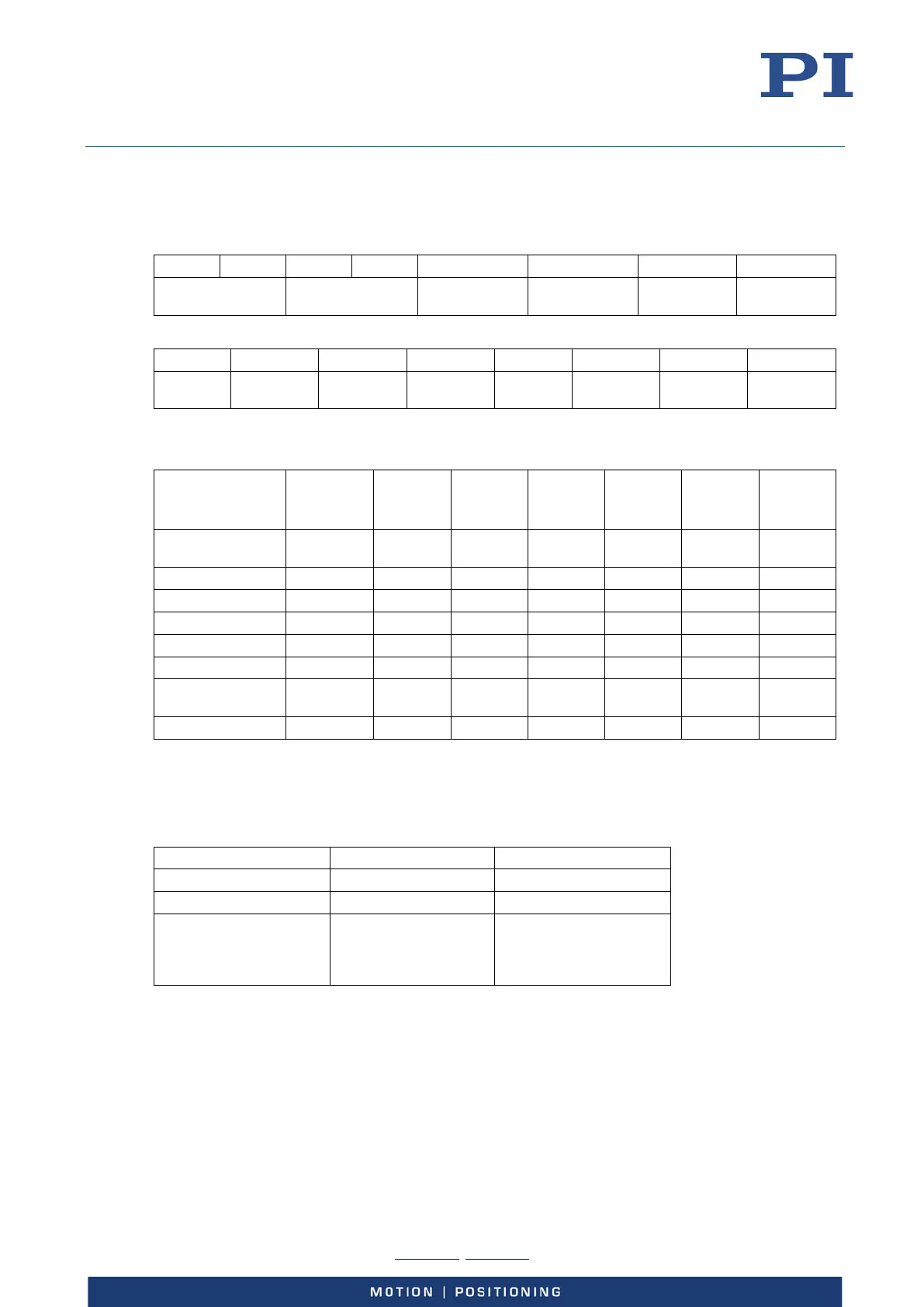
Status Word
The status word (object 0x6041 for the first axis, object 0x6841 for the second axis, …) contains bits
for the following information:
15 14 13 12 11 10 9 8
Manufacturer
specific
Operation mode
specific
Internal limit
active
Target reached Reserved
Manufacturer
specific
7 6 5 4 3 2 1 0
Reserved
Switch on
disabled
Quick stop
Voltage
enabled
Fault
Operation
enabled
Switched on
Ready to
switch on
Table 4: All bits of the CiA402 status word
Bits 0 to 6 show the state of the drive state machine:
State Bit 6 Bit 5 Bit 4 Bit 3 Bit 2 Bit 1 Bit 0
Switch on
disabled
Quick stop
Voltage
enabled
Fault
Operation
enabled
Switched
on
Ready to
switch on
Not ready to switch
on
0 x 0 0 0 0 0
Switch on disabled 1 x 0 0 0 0 0
Ready to switch on 0 1 1 0 0 0 1
Switched on 0 1 1 0 0 1 1
Operation enabled 0 1 1 0 1 1 1
Fault 0 x x 1 0 0 0
Fault reaction
active
0 x x 1 1 1 1
Quick stop active 0 0 1 0 1 1 1
Table 5: Bits 0 to 6 of the CiA402 status word
Bit 10 shows the on-target state. Details differ depending on the selected mode of operation.
The meaning of bits 12 and 13 depends on the selected mode of operation. For the modes of
operation supported by the E-727, these bits show the following:
Bit / Operation mode 13 12
Homing Homing error Homing attained
Profile Position Reserved* Setpoint acknowledge
Cyclic Synchronous Position Reserved* 0 = Target position ignored
1 = Target position shall be
used as input to position
control loop
*Bit 13 is always 0.
Table 6: Bits 12 and 13 of the CiA402 status word
Bits 7, 8, 9, 11, 14 and 15 are not used at present.