User Manual
E727T0005, valid for E-727
BRO, 2019-06-28
Physik Instrumente (PI) GmbH & Co. KG, Auf der Roemerstrasse 1, 76228 Karlsruhe, Germany Page 22 / 240
Phone +49 721 4846-0, Fax +49 721 4846-1019, Email info@pi.ws, www.pi.ws
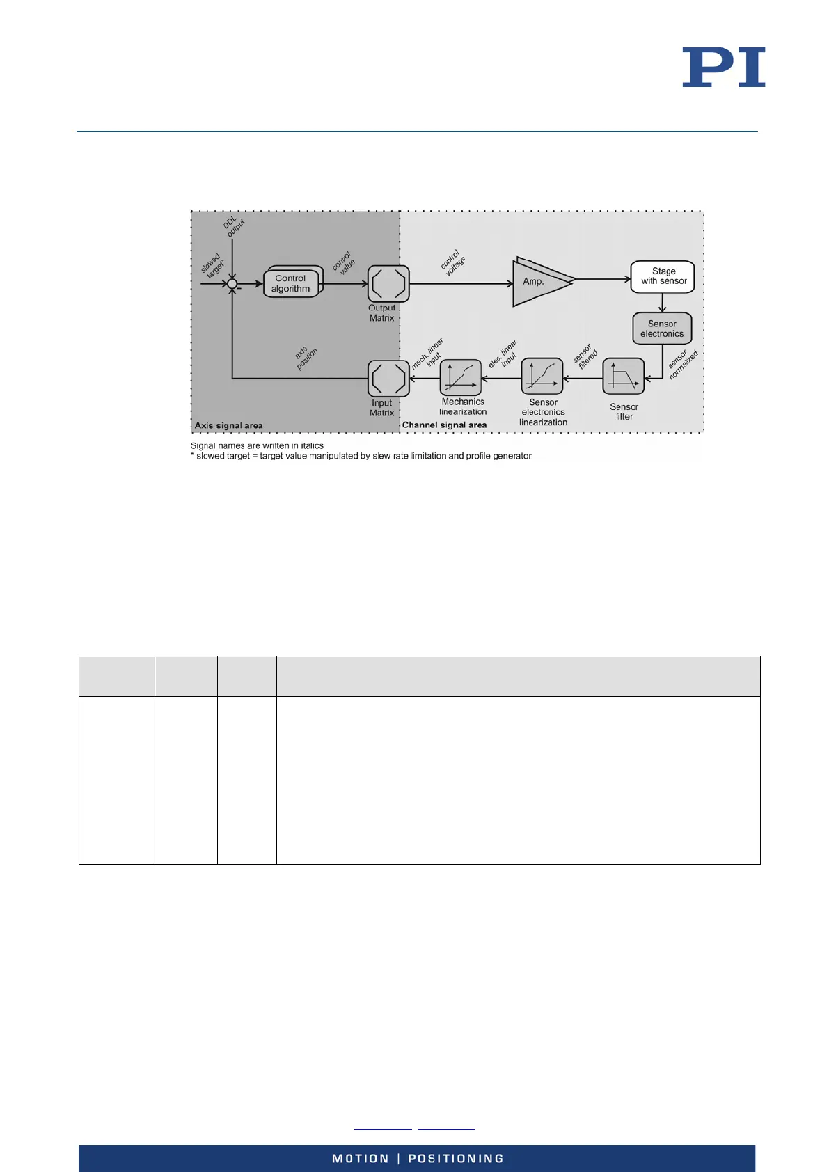
The E-727 controls the motion of the logical axes of the connected stage(s) in open-loop or closed-
loop operation. The block diagram below shows the signal path for an axis in closed-loop
operation.
Figure 6: Block diagram of an axis in closed-loop operation
Axes, Channels, Functional Elements
The following table contains the items that can be accessed with commands of the PI General
Command Set (GCS).
When controlled by an EtherCAT master (E-727.xxxF and .xxxAF only), the EtherCAT master
specifies target positions for the logical axes of the E-727. For further information, see "EtherCAT
Interface" (S. 164).
Item Num-
ber
Identi-
fier
Description
Logical
axis
3 or 4 1 to 3
or
1 to 4
The supported number of logical axes depends on the E-727 model.
The logical axes represent the motion of the stage in the firmware of the E-
727. A logical axis corresponds to an axis of a linear coordinate system.
All commands for the motion of a stage refer to logical axes.
The value of the Number Of System Axes parameter (ID 0x0E000B02)
specifies the number of axes.
The input and output signal channels of the E-727 are allocated to the
logical axes via matrices (input matrix: parameters 0x07000500 to
0x07000506; output matrix: parameters 0x09000000 to 0x09000003).