User Manual
E727T0005, valid for E-727
BRO, 2019-06-28
Physik Instrumente (PI) GmbH & Co. KG, Auf der Roemerstrasse 1, 76228 Karlsruhe, Germany Page 36 / 240
Phone +49 721 4846-0, Fax +49 721 4846-1019, Email info@pi.ws, www.pi.ws
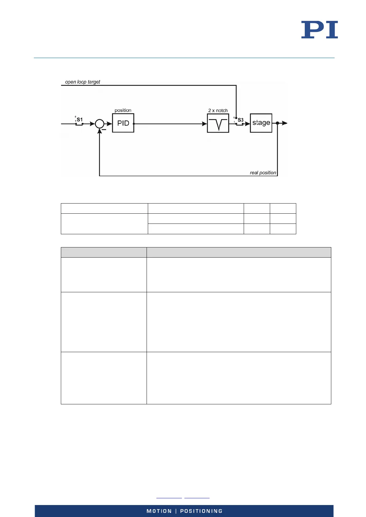
Position control (parameter value = 1):
Figure 14: Control structure for position control (mode 1). Here it is assumed that the notch filters are
disabled in open-loop operation (default setting of the Enable Notch In Open-Loop parameter).
Position control (mode 1) Open-loop operation 0 0
Closed-loop operation 1 1
The PID algorithm can be configured with the following parameters:
Parameter Notes
ID 0x07000300
P constant for position control
Must be > 0.
For further details, see “Servo-Controller Dynamic Tuning”
(p. 131).
ID 0x07000301
Integrator time constant Ti for position control
output = Ts / Ti ∙ ∑ input
where Ts is the servo update time (parameter 0x0E000200).
When the time constant Ti is zero, then the integrator is turned
off.
For further details, see “Servo-Controller Dynamic Tuning”
(p. 131).
ID 0x07000302
Differentiator time constant Td for position control
output = Td / Ts ∙ Δinput
where Ts is the servo update time (parameter 0x0E000200).
Must be > 0.
For further details, see “Servo-Controller Dynamic Tuning”
(p. 131).