Figure 8A-11. Aligning Timing Marks Figure 8A-12. Checking Flyweight Clearance of
Impulse Coupling
4. Install the 11-8693 Timing Plate Assembly and the 11-8149 Pointer Assembly of the 11 - 8 1 5 0
Scintilla Timing Kit to breaker compartment of magneto. (Refer to Figure 8A-10.) Align pointer
assembly with the 0 mark on timing plate. Loosen adjusting knob of 11-8465 Rotor Holding Tool
and turn rotating magnet in normal direction of rotation until pointer indexes with the respective E
gap mark (15° ± 2°). Tighten adjusting knob of 11-8465 Tool and remove the 11-8149 Pointer
Assembly from magneto. Using a timing light, adjust contact points to just open. This adjustment
shall be made by rotating cam, in opposite direction of rotation until contacts just open. While
holding cam in this exact position, push cam on magnet shaft as far as possible with the fingers.
Extreme care must be exercised in this operation. If cam adjustment is changed in the slightest
degree, the timing of the magneto will be thrown off. Do not drive cam on shaft with a mallet or
other instrument. Tighten the securing screw thereby drawing the cam down, evenly and tightly.
Torque screw to 16-20 inch-pounds. Loosen the 11-8465 Rotor Holding Tool adjusting knob and
return rotating magnet to neutral position. Reinstall the 11-8149 Pointer Assembly over 0 mark on
timing plate. Rotate magnet shaft in normal direction of rotation and check for opening of main
contact points at E gap setting (15° ± 2° ).
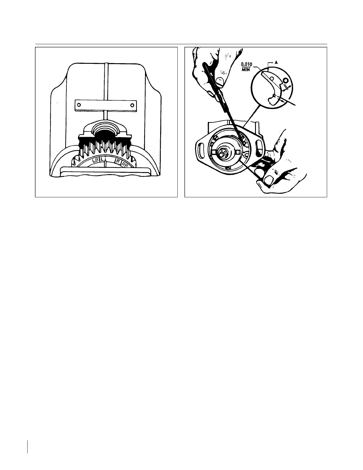
c. If the distributor block was not removed from the housing, the internal timing may be checked by
turning the magneto in the normal rotation to number one firing position (keyway up and points just
opening). At this position, the reference line on the distributor block should line up between the L and
LB marks on the gear. On single contact magnetos the line should favor the L mark, if possible.
d. If the distributor block was removed from the housing, the distributor gear alignment and internal
check may be accomplished as followed:
1. Turn rotating magnet in direction of rotation until it is located in firing position (keyway up and
points just opening). Tighten adjusting knob of 11-8465 Rotor Holding Tool. Apply a light coating
of Bendix Grease P/N 10-27165 to teeth of distributor gear, if needed. The large distributor gear
incorporates four timing marks, L and LB for left-hand rotation and R and RB for right-hand
rotation.
2. With distributor gear assembled to block, turn gear until raised rib on block lines up between the L
and LB marks. Assemble block and gear into housing, meshing the distributor gears together. The
rib should favor the L mark, if possible. (Refer to Figure 8A-11.)
Revised: 8/31/77
2D15
CHEROKEE ARROW III SERVICE MANUAL
POWER PLANT - LYCOMING