USER MANUAL
URM18PH392 Rev A. May 2020 Page 71 of 86
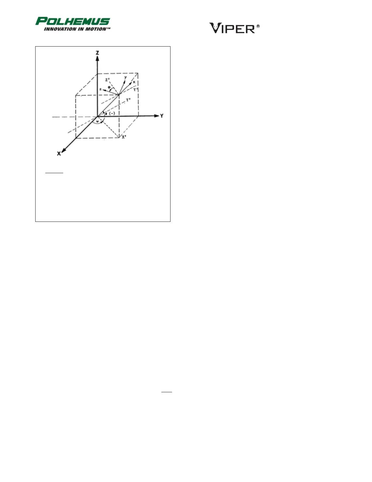
The Euler angle coordinates that are output by VIPER™ as
one measure of Sensor orientation are graphically defined in
the figure below. Here, the x, y, z and X, Y, Z tri-axis arrays
represent independent, three-dimensional orthogonal
coordinate frames. The x, y, z triad represents the Sensor
frame in its current orientation state. The X, Y, Z triad
represents the reference frame against which the relative
orientation of the Sensor frame is measured. By definition,
the X, Y, Z frame also represents the zero-orientation
reference state of the Sensor frame.
The Euler angles azimuth, elevation and roll, are designated
, , and . These angles represent an azimuth-primary
sequence of frame rotations that define the current
orientation of the Sensor with respect to its zero-orientation
state. The defining rotation sequence is an azimuth rotation
followed by an elevation rotation followed by a roll rotation.
The azimuth angle is defined in the figure as a rotation of
the X and Y reference axes about the Z reference axis. The
transition axes labeled X’ and Y’ represent the orientation of
the X and Y axes after the azimuth rotation.
The elevation angle is defined as a rotation of the Z
reference axis and the X’ transition axis about the Y’ transition axis. The transition axis
labeled Z’ represents the orientation of the Z reference axis after the elevation rotation.
The current x-axis of the current Sensor frame represents the orientation of the X’
transition axis after the elevation rotation.
Last, the roll angle is defined as a rotation of the Y’ and Z’ transition axes about the x-
axis of the Sensor frame. The y and z-axes of the current Sensor frame represent the
orientation of the Y’ and Z’ transition axes after the roll rotation.
In the diagram above, the azimuth, elevation and roll rotations are positive, negative
and positive respectively.
Output List A list of the data items included in a data record.
Parity In serial communication, a parity bit may be added to each transmitted byte to check
whether corruption has occurred. Serial port configuration may set parity to None,
Even, or Odd. During transmission, the sender calculates the parity bit and sends it. The
receiver calculates parity and compares the result to the parity bit received.
Persistent Setting Tracker settings that may be stored in VIPER™ flash memory so that they will persist
through power-cycle or soft reset. (These settings are not automatically persisted,
however. A PERSIST operation must be performed to store the settings to flash.)
P&O Acronym for position and orientation, the six pieces of data needed to fully describe
tracking of an object in 3D space. Some tracking devices, by virtue of their principle of
Legend
X, Y, Z = Alignment (Reference) Frame
x, y, z = Rotated Stylus or Sensor Coordinate
= Azimuth
= Elevation
= Roll