Polycom, Inc. 8
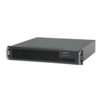
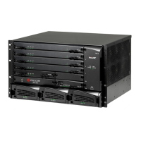
KIRK Wireless Server 8000 and KIRK Wireless Server 2500 System Overview Overview
Overview of Front LEDs
The following tables describe the status LEDs for each card.
Table 2-3 CPU Card Ethernet Connector LEDs
Table 2-2 LEDs Common to all Modules
LED Name Location Color Description
POWER On top of all
modules
Green Steady green light
when the power is
on and the card is
running.
POWER On top of all
modules
Red Flashing red light
at power up.
Steady red light in
case of error.
Note
On CPU card without link, the POWER LED is signalling the IP address of KIRK
Wireless Server 8000 (or KIRK Wireless Server 2500) by means of a sequence of LED
flashing different colors.
Below is an example of behavior for IP address 127.0.1.101:
• LED steady green (“beginning of message”); LED off (break); LED flash blue
(ignore this)
• The power LED morses the IP address. The morse cycle for the power LED is as
follows: Steady green 30 seconds, Blinking blue 3 seconds (get ready sequence
starts) Green blink represents digits (zero is a long blink). Red means dot
between digits.
• break, LED flash green once (=”1”), break, LED flash green twice (=”2”), break,
LED flash green 7 times (=”7”), break, LED flash red (=”.”)
• break, LED flash green once, longer (=”0”), break, LED flash red (=”.”)
• break, LED flash green once (=”1”), break, LED flash red (=”.”)
• break, LED flash green once (=”1”), break, LED flash green once, longer (=”0”),
break, LED flash green once (=”1”), break
• LED steady green (“end of message”)
LED Name Location Color Description
Link At the bottom of
all modules
Yellow Steady yellow
when the Ethernet
connection is in
sync.
Activity At the bottom of
all modules
Green Flashing green
light when the
Ethernet
connection is
active.