18
Installation
4.4 Mounting the analyzer
CAUTION
Wherever the analyzer is to be mounted, it is important to note that it must be placed in
an upright position with the transmitter at the top. It is recommended to use a spirit level
to ensure that the analyzer is correctly positioned and not leaning to one side or forward.
This is essential to guarantee the accuracy of the analyzer.
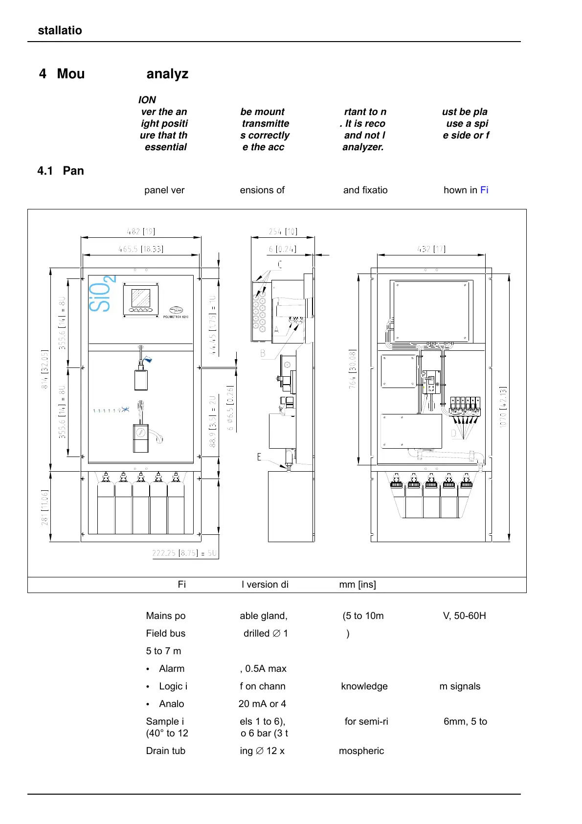
4.4.1 Panel version
For the panel version, the dimensions of the analyzer and fixation holes are shown in Figure 4.
A. Mains power supply cable gland, drilled ∅ 11 (5 to 10mm), 100…240V, 50-60Hz, 25VA
B. Field bus cable gland, drilled ∅ 13 (6 to 12mm)
C. 5 to 7 mm cable gland
• Alarm signals: 30V, 0.5A max.
• Logic inputs: Cutoff on channels 1 to 6, acknowledgement of alarm signals
• Analog outputs: 0-20 mA or 4-20 mA
D. Sample inlets, (channels 1 to 6), QR coupling for semi-rigid tubing ∅ 6mm, 5 to 50°C
(40° to 120°F), P 0.2 to 6 bar (3 to 87 PSI)
E. Drain tube: silicon tubing ∅ 12 x 17mm, at atmospheric pressure
Figure 4 Panel version dimensions - mm [ins]