19
Installation
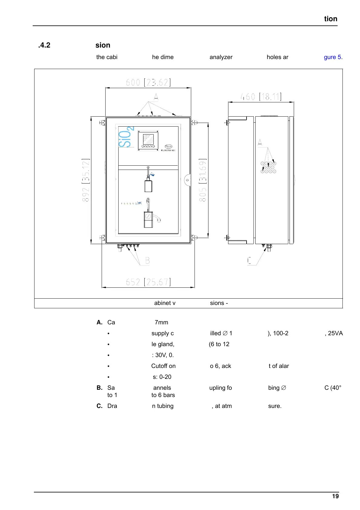
4.4.2 Cabinet version
For the cabinet version, the dimensions of the analyzer and fixation holes are shown in Figure 5.
A. Cable gland, 5 to 7mm
• Mains power supply cable gland, drilled ∅ 11 (5 to 10mm), 100-240V, 50-60Hz, 25VA
• Field bus cable gland, drilled ∅ 13 (6 to 12mm)
• Alarm signals: 30V, 0.5A max.
• Logic inputs: Cutoff on channels 1 to 6, acknowledgement of alarm signals
• Analog outputs: 0-20mA or 4-20mA
B. Sample inlets (channels 1 to 6), QR coupling for semi-rigid tubing ∅ 6mm, 5 to 50°C (40°
to 120°F), P 0.2 to 6 bars (3 to 87 PSI)
C. Drain tube: silicon tubing ∅ 12 x 17mm, at atmospheric pressure.
Figure 5 Cabinet version dimensions - mm [ins]